Some possible additional pictures to be used, but I haven't the actual figures to use available at the moment:
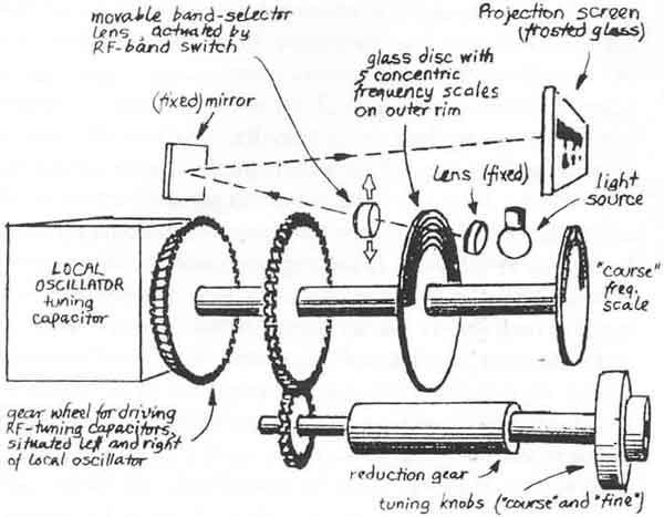
Fig 1-2. Principle of frequency read-out system
PA0SE (E52 part one)
pg 12a
German WW2 Radio equipment
[Scanned by LA5FH]
Technical articles under
preparation (received from PA0SE Dick Rollema):
This is the third of a series of three
articles. The first one, German World War II Radio Equipment,
appeared in RB65
and described the German technology with aircraft radio equipment
FuG 10 as an example.
The second article was titled Lorenz. Short Wave Receiver Lo6K39a
- The Ultimate Tuned Radio Frequency Set and was featured in
RB72. We will end this trilogy with a description of a remarkable
superheterodyne receiver, made by Telefunken. The photo below
shows the radio. The name Köln (Cologne) was chosen as the
project designation for what eventually became a short-wave
communications receiver that may be considered as being the
finest ever developed and built during the Second World War. The
receiver was designed by Telefunken at the beginning of the war
for the German military forces and represents a true example of
the state of the art at the end of WWII.
10a Introduction
to German World War II Radio Equipment
(FuG10)
12a. German World War II Radio Equipment - Köln
E52 receiver - part 1 (PA0SE Dick Rolema)
12b. German World War II Radio Equipment - Köln
E52 receiver - part 2 (PA0SE Dick Rolema)
12c. Lorenz Shortwave Receiver Lo6K39a
(Lo6L39), The ultimate TRF set [PA0SE]
12d. Telefunken World
War II Superheterodyne Receiver Kw.E.a (Lw.E.a)
[PA0SE]
12e. Telefunken World War II Universal TRF receiver Torn.E.b
[PA0SE]
Planned page, some possible faults to be corrected when I have
the manus returned
Tyrkleif de LA5FH (to be checked when LA6NCA returns the papers):
E52-1:
Under tittelen STRATEGIC...: 8x10⁻⁶
Under tittelen SPCIFICATION...: 30x10-6 (Den er plassert bakerst
i del 1)
Omega rettet til ohm
Telefunken World War II
Superheterodyne Receiver E52 'Köln'
HISTORY
In the years just before the outbreak of WWII German industry, as
well as their military principals, were convinced that at least
in Germany the art of building communications receivers for
frequencies up to 30MHz had reached a point where no further
technical development of importance was to be expected in the
foreseeable future. Therefore, instead of allowing a further
proliferation of receiver types, which could bring little more
than minor improvements in size, weight or control convenience,
the German Air-Transport Ministry decided in 1939 to introduce a
new receiver for the Luftwaffe (Air Force) terrestrial
communications that should become the standard communications
receiver.
The exacting specifications for the radio set called for a truly
advanced product that, besides showing supreme electrical
qualities capable of passing the test of many years to come, also
had to be of sound and uncomplicated mechanical design.
Particular emphasis was placed on production by an industry that
possibly could be forced to strategically spread over different
geographical locations.
Thereupon, Telefunken, the most important German manufacturer of
radio equipment at the time, and being one of the tenderers for
the ambitious project, developed the prototypes of four
receivers. They were all similar looking in outward appearance
and code-named after the German towns of Leipzig (40-1600kHz),
Köln (1.5-25MHz), Ulm (2468MHz), and Kulm (60-150MHz). Early in
1941, entering their second year of the war, the Luftwaffe
accepted the Köln, whilst the receiver was also recommended to
be adopted by the Army, the Wehrmacht. Consequently, the Köln
went into production, later followed by the Ulm. The Leipzig (a
long-wave double superhet with 2MHz and 130kHz IF), and the Kulm,
never made it to the production line, as far as known. Thus, with
their Köln, soon registered under the Luftwaffe nomenclature of
'E52'. Telefunken introduced 'The Ultimate Communications
Receiver' as it was intended to remain for many future years. And
it certainly did, as turned out later.
Taking stock of electronic technology as it existed immediately
after the war in 1945, there could be little doubt that the E52
was still one of the most advanced radio receivers of its time.
Even during many years following WWII, nowhere in the world, so
it seemed, was there a series-produced article to be found that
could match this receiver. Today, of the approximately 2500 Köln
(E52) short-wave receivers produced, only a rather limited number
are still in existence, although in most cases perfectly
serviceable and cautiously guarded by some of the more fortunate
connoisseurs of German radio equipment. These relatively few
precious sets miraculously survived the war, as well as the
succeeding mania of senseless destruction of 'former-enemy radio
equipment' as ordered by some of the Allied military commanders
after the German capitulation. However, what does appear to have
been definitely lost, unfortunately, are many details of an
impressive research that stood at the beginning of the highly
advanced technology that made it all possible.
GERMAN TECHNOLOGY
In the first article of this series (RB65)
it was shown in what aspects German radio technology was
different from what was more or less standard in other countries.
They can all be found in the Telefunken E52. We repeat them here:
1. Instead of a metal chassis, a die-cast frame of a special
aluminium alloy was used. Into this frame, modules housing
different parts of the electronic circuitry could be bolted or
clicked together. The modules could be manufactured at the most
suitable production site, even being tested and calibrated there.
2. Coils with iron dust cores or of silver windings burned onto a
ceramic former.
3. Ceramic capacitors with controlled temperature coefficient.
4. Limited number of valves.
The first article also described why the Germans favoured tuning
by means of variable oscillators over crystal control. This
aspect is so important that we pay some attention to it again.
In September, 1936, Hitler launched his '4 Year's Plan', thus
making the German economy subordinate to a general preparation
for war. It was Goering who received the virtually unlimited
power for realising this plan. Also for the electronic production
this led to important consequences, like the reminder to the
German industry of its dependence on foreign basic materials.
One of these was quartz. Brazil, being the sole world quartz
producer of importance, was geographically too far away from
Germany for a reliable supply to be secured in times of war.
Consequently, the industry took up the challenge of finding new
solutions, avoiding the use of quartz where possible,
nevertheless aiming at meeting the strict frequency stability
specifications as laid down by their military customers. What
eventually emerged was a development that did not lead to what
one could easily have expected to become an ersatz solution.
Instead it turned into a victory of electronic hardware
technology. Temperature-compensated variable oscillators of
exceptional frequency stability were the result. Though primarily
developed to replace quartz crystals in transmitters, the
technology was also applied to variable oscillators used in
superheterodyne receivers like the E52.
BLOCK DIAGRAM
The antenna (Figure 1) is followed by a double-tuned band-pass
filter that drives the first RE amplifier. Next comes another
double-tuned band-pass filter, feeding the second RE amplifier.
Then follows a single tuned circuit and the mixer that converts
the incoming signal to the 1MHz IF. The mixer also receives the
signal from the local oscillator. The five preselector circuits
and the local oscillator are tuned by the sections of a six-gang
variable capacitor.
Directly following the mixer is a fixed tuned IF filter with no
fewer than six circuits. Next comes the first IF amplifier, a
crystal filter with continuously variable bandwidth, the second
IF amplifier, again a crystal filter, the third IF amplifier and
a single tuned circuit that feeds the detector circuit for audio
and AGC voltage. When used for reception of telegraphy the signal
from the beat frequency oscillator (BFO) is also fed to the
detector. The oscillator frequency can be adjusted from the front
panel; but it can also be controlled by a quartz crystal on
1000.9kHz. When crystal controlled, the oscillator also provides
calibration signals. Finally, an audio amplifier brings the
signal up to headphone level. We will now take a closer look at
the details of the E52 receiver.
THE RF CIRCUITS
Not unlike many other Wehrmacht receivers at the time, the RF
preselection of the E52 is impressive. No fewer than five tuned
circuits, divided over two band-pass filters and a single tuned
circuit, precede the mixer stage. This extremely high RF
selectivity was not unusual in German communications receivers.
It results not only in an exceptionally high 'second-channel' or
image frequency suppression (thus blocking those unwanted RF
signals at a different frequency which happens to produce the
same IF), also the receiver shows no trouble with any 'intercept
point' which today seems to occupy the mind of so many receiver
manufacturers. In fact, it would not be difficult to demonstrate
how the RF section of the E52, working on its own, would exhibit
sufficient selectivity for use as a high-quality straight Tuned
Radio Frequency (TRF) receiver. And that in spite of the slightly
unequal bandwidth of the RF band-pass filters, owing to the
unavoidable frequency-dependent coupling factor of the tuned
circuits.
It is not impossible that this comprehensive RF pre-selection in
military receivers stems from a historically grown prejudice. It
appears that in pre-war German military circles a certain feeling
existed against the principle of the superheterodyne receiver,
mainly because of the inherent danger of this second-channel
interference. It is known, for example, how in particular the
German Kriegsmarine (Navy) objected persistently against the
introduction of the superhet, even until as late as around the
outbreak of WWII. (Incidentally, this mistrust led to some
spectacular designs of TRF receivers, as for instance the Lorenz
L06K39a, discussed in RB72). The anxiety could also stem from the
fact that on shipboard, several transmitters and receivers can be
in operation at the same time which could easily result in
spurious responses of a superheterodyne receiver. In a TRF
receiver this possibility is almost absent. It is also rumoured
that the Kriegsmarine feared that the radiation of the local
oscillator in a superheterodyne could be used by the enemy to
locate the receiver by means of direction finding. But we have
found no confirmation of this in the available literature. If
there was a way to prove that second-channel interference in
superhets could be reduced to harmless levels, the factory
specification for the E52 of better than 94dB at 20MHz (worst
case) was convincing indeed. Likewise, the IF suppression was
highly effective: at 1.5MHz (worst case) better than l00dB. The
ganged tuning capacitors, mounted along the full width of the
main frame, show high precision and stability. For the six-ganged
variable capacitor, including the section for the local
oscillator unit, at any position over the entire range between 0
and 180 degrees, the deviation in capacity between any of the
sections does not exceed 0.25 percent. The rotor plates of the
capacitors are crimped onto a ceramic shaft, the stator plate
units attached to the metal frame by ceramic stand-offs. This
permitted a compact construction and, in spite of the consequent
smaller spacing between the plates, production tolerances could
be reduced and the temperature coefficient improved. The five
tuning capacitors for the RF-input circuits are divided into two
groups, with the dual 90° mechanical coupling to the main shaft
of the receiver tuning unit in between them. The conical gear
wheels are, as a matter of course, of the spring-loaded
anti-backlash type.
The way the coils are arranged still betrays something of the
traditional preferences of the Wehrmacht radio designers for
rotating coil turrets rather than using RF bandchange switches
with their inherent contact and spuriouscapacity problems. Coil
turrets were a German speciality and many examples can be found
of Wehrmacht receivers containing such masterpieces of
coil-rotating mechanisms. In the E52, however, no turret is used,
and it proves that Telefunken could also produce switches of
excellent quality. Thus, in the E52 the contacts are not situated
around the coils, but the coils are placed around the switch
contacts. The shaft of the band switch runs along the full frame
width, and has been extended at the left-hand side of the
cabinet. This permits a mechanical coupling with switches in a
possible receiver attachment like, for example, a direction
finder. In a similar manner, the tuning-capacitor shaft can
mechanically drive the loop-tuning capacitor in the
direction-finder tuning unit.
THE TUNING MODULE
The die-cast frame of the tuning module contains the variable
local oscillator capacitor, two electric motors, a highly
accurate mechanical 'memory' for storing receiver frequencies, as
well as an unusual frequency read-out device where the frequency
scale is displayed on a glass screen situated at the top of the
receiver cabinet. The memory, and the method of frequency
read-out, must he one of the most sophisticated designs created
for a military radio receiver in WWII. See Fig. 2. The tuning
knob drives, via a mechanical reduction, a sturdy main shaft
which controls directly the critical elements. The crucial point
about the design is that any backlash between the local
oscillator capacitor and the tuning indicators is simply
impossible. The reason for this is that the pointer for the
'coarse' scale (the half-round disc just above the tuning knob),
the glass disc containing the 'fine' scale, inside the module,
and the rotor plates of the tuning capacitor, are all, directly
and immovably, fixed onto the same main tuning shaft.
It is this particular concept of using light as a medium, and
avoiding any form of mechanical translation, that permits the
highly magnified and yet intrinsically rock-solid and precise
'fine' frequency read-out, which makes the E52 such a unique
radio receiver. The frequency scale is projected onto a small
rectangular ground-glass screen (illuminated from behind) located
above the tuning knob and 'coarse' indicator. The total absence
of backlash, combined with the highly effective temperature
compensation of the associated tuned circuits, as well as an
individual frequency calibration at the factory to remove the
last component tolerances, result in an accuracy that, certainly
in its time, was unheard of.
The information of the frequency scales of all five bands is
stored on the outer 6mm rim of a glass disc of about 100mm
diameter. This glass disc is safely mounted inside the sturdy
framework of the module. The extremely fine print on the disc was
achieved by using microfilm techniques. The information is
projected by a narrow light beam passing through the selected
portion of the glass rim (depending on the position of the band
switch) via a lens. The light originates from a low-voltage
projection lamp (located just under the projection screen) and
is, before it passes through the glass disc, focused by another
lens towards the rear of the module where it is reflected by a
mirror. Thus, not only a complete projection system has been
realised in a compact space, even the projection lamp, a
dispensable item like the valves, can he replaced without opening
up or moving the radio set.
PRECISION OF THE SCALE
The precision and stability of the frequency scale of the E52 may
he considered as being the best that can he achieved in a
mass-produced mechanical analogue system. Yet, each of the five
projected frequency scales - of which at any time only a section
of a few centimetres is displayed - represents a full length of
more than 1.8 metres! Of course, the extreme accuracy of this
superb opto-mechanical system had its price. At the factory, for
each receiver the projection disc had to he individually
calibrated and photo-printed. Resulting from this calibration, of
each disc four identical copies were produced. One was mounted
into the tuning module of the receiver to which it belonged,
another copy was safely hidden against the backwall of the
receiver cabinet as a spare, a third copy was kept at the
factory, while the last one was stored at a central military
depot in Germany. In this way, the frequency-scale information on
the glass disc, the precious heart of the tuning mechanism, was
considered to be best safeguarded against damage or loss. What a
highly expensive and elaborate system it must have been, only
possible in a situation where an industry, set out to produce the
very best possible, irrespective of any reasonable economical
consideration, knew itself fully backed by their plutocratic
principals.
There were limits, though. With the war progressing, and
suffering from the effects of the increasing bombardments
reaching ever deeper into Germany, the E52 receiver production
also began to feel the stress and had to yield to certain
compromises. At a later stage of the war, the system had to be
simplified.
It seems that at Telefunken, the aim for the utter technical
limit in the production specifications more than once brought the
industry into deep trouble. Instances occurred where the
specifications turned out to be too highly strung, once the
production was on its way. Permitted tolerances which general
have a tendency to even out, do sometimes add up, and in these
cases there was little or no room left for correction. Solving
the consequent problems required tremendous efforts during the
manufacturing process and indeed, it would appear that certain
supply bottlenecks were not always unwelcome as they provided the
justification for the inevitable modifications necessary for
keeping the production flowing. Eventually, at the main
production lines the luxury of turning out individually
calibrated frequency scales for the E52 had to be abandoned, and
later models had to be issued with universal scales, based upon a
limited number of typical 'average' calibration patterns (these
scales can be recognised by their black-on-white print, instead
of white-on-black). It speaks for the overall production
tolerances that the accuracy of even these simplified receivers
nevertheless remained extraordinary high.
TEMPERATURE COMPENSATION
It is one thing to produce a frequency read-out with a high
resolution, but this is of little use if the calibration is not
maintained with changing temperature. In RB65 it was told that
the German firm Herinsdorf-Schomburg-IsolatorenGesellschaft, also
known as Hescho, in the 1930s managed to produce ceramic
capacitors with a controlled temperature coefficient. These made
it possible to compensate the variations with temperature of
inductance and capacitance of the components in an oscillator
circuit. The local oscillator temperature compensation in the E52
is, as customary in most Wehrmacht receivers, effected by a
combination of capacitors with a negative temperature
coefficient, both in parallel and in series with the tuned
circuit of the local oscillator, in order to make the
compensation correct at all positions of the tuning capacitor.
Each compensating capacitor is composed of several tubular
capacitors, connected in parallel, selected for their
(colour-coded) temperature coefficients. These
capacitor-batteries are physically located at strategically
chosen positions in the frame to take into account both frameend
ambient temperature variations. The many capacitors together
represent a large exposed surface with fast reaction time, while
the distribution of their different temperature coefficient
figures shape the correct compensation.
STRATEGIC SIGNIFICANCE
As an aside: Has the strategic significance of these industrial
developments ever been evaluated by Allied Bomber Command when
they were picking their targets? It was mainly owing to the
spectacular progress in these technologies, far ahead of anywhere
else in the world, that the German Kriegsmarine (Navy) could be
equipped with compact transmitters with free-running variable
master oscillators (with valves!) that demonstrated overall
frequency stability specifications - without the use of quartz -
of better than 8 x 10⁻⁶ °C. Or, for a better appreciation of
this figure: it was this order of accuracy that enabled the
German submarines to apply their tactics of 'blind' high-speed
communication in foreign waters. This example of precision had to
be performed during a surfacing manoeuvre, lasting only seconds,
at an exactly pro-determined hour and frequency an operation that
excluded any tuning correction as the idiosyncrasy of the German
'Enigma' ('Ultra') coding system could not permit the loss of any
single code character during a transmission.
Part Two of this article will continue the
in-depth examination of this exceptional receiver.
| Specifications for the E52 'Köln' | |
| Frequency ranges | 1480-3020kHz 2980-6040kHz 5975-10050kHz |
| 9950-17700kHz 17600-25200kHz |
|
| Modes: | A1A, A2A, A3 optional FM, SSB, TV |
| Power requirement | 110-230VAC 50-60Hz, or 12VDC |
| Dimensions | 245mm x 446mm x 350mm |
| Weight | 40,8kg |
| Sensitivity |
AM (wide) 3,5µV CW (wide) 1µV CW (narrow) 0,3µV |
| Image rejection | Better than 94dB @20MHz |
| IF rejection | Better than 100dB |
| Antenna | 60/150 ohm |
| IF | 1000kHz BFO: 1000,9kHz |
| Bandwidth |
continuously variable
between 10kHz (-3dB), 26kHz (-60dB) |
| and 200kHz (-3dB), 4kHz (-60dB) | |
| Frequency stability | better than 30 x 10 E-6 °C |
Some possible additional pictures
to be used, but I haven't the actual figures to use available at
the moment:
Fig 1-2. Principle of frequency read-out system
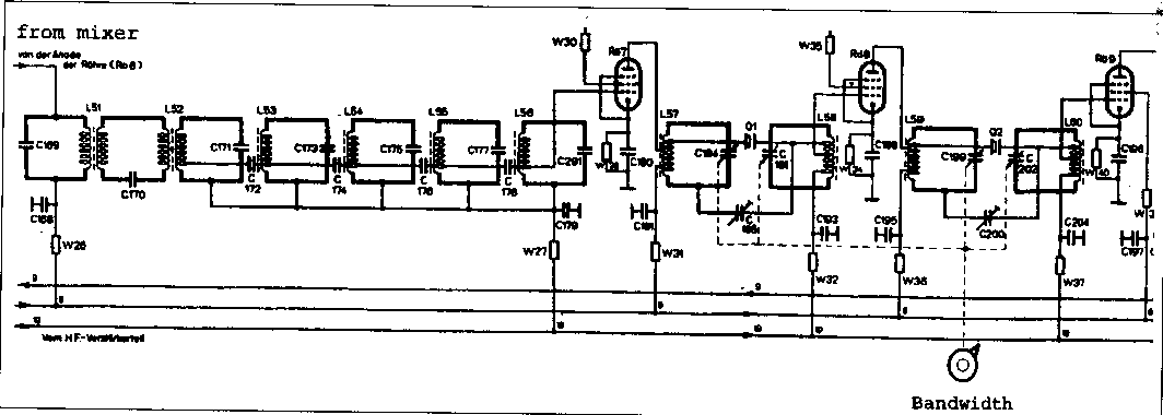
fig 2-6 IF filter circuit
 e/m
e/m
2004.03.02