Kw.E.a front view (LA8AK)
pg 12d
German World War II Communications Receivers
Technical Perfection From A Nearby Past
Part III of this elongated series concerns itself with the
Kw.E.a superheterodyne receiver which was a basic Telefunken
design.
[Scanned by LA5FH]
Tyrkleif de LA5FH
(printning mistuakes to be chekced when LA6NCA returns the
papers)
KwEa:
1. avsnitt: un.....ld. Unleselig ord, jeg tør ikke tippe(!)
Kw.E.a front view (LA8AK)
KwEa seen from above (LA8AK)
Kw.E.a (Lw.E.a)
BY DICK ROLLEMA, PA0SE
Part III now takes up with a 1938 design for a superheterodyne
receiver. The Kw E a as you will see from the photos is a marvel of
mechanical engineering. While PA0SE regales us with the
theoretical aspects of the design, one can only imagine how that
was transformed into the mechanical beauty we see un.........ld. Still, the thought of lugging 77 pounds of hardware
around leaves a lot to be desired.
K2EEK
SHORT WAVE SUPERHET Kw E a
The first of the two superheterodyne receivers we are going to
discuss is the Kw E a (Kw = "Kurzwellen" = short wave,
E = "Empfanger" = receiver, a is serial indicator).
This radio was designed by Telefunken and it became operational
in 1938.
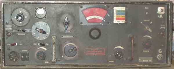
Photograph 8 gives you a first impression of what it looks like.
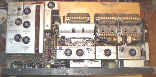
Photograph 9 shows the receiver out of its cabinet and photograph
10 a rear view.
The dimensions of the radio are 69.2 cm wide, 27.4 cm high and
34.6 cm deep. It weighs 38 kg (77 lbs). Not directly a set to
take on holidays.
The total frequency span of 1 to 10 MHz is covered in five
ranges, as follows: 980-1610 kHz; 1560-2550 kHz; 2470-4060 kHz;
3940-6395 kHz and 6205-10000 kHz. Again the subbands are kept
relatively narrow which improves the ease of tuning and the
frequency read-out
Looking at photograph
8 you notice several by now
familiar features. Left of the dial the band-selector control
above ("Grob" = coarse) and main tuning control with
crank ("Fein" = fine) below. The dial features the
rotating mask we already met on the previous receiver with a slot
that displays only the frequency scale in use. The mask also
shows the limits of the selected range and the frequency
increment that corresponds to one dial division, 10 kHz on range
III, as seen in the photograph. The receiver uses the same
filament type tube in all 11 stages. It is the type RV 2 P 800
pentode we also encountered in the Torn E b. The radio consumes
1.6 a. at 2 v. for the filaments and 15-20 ma. at 90 v anode
current. The bottoms of the tubes with extraction knob can
clearly be seen in photographs 9 and 10.
The simplified diagram in the instruction manual is too
complicated to reproduce here. Therefore we present a block
schematic diagram as fig.
8.
The mixer is preceded by two r.f. amplifier stages. There are
five tuned r.f. circuits that are ganged to the oscillator tuning
circuit. The user has the option to use a single or a double
tuned circuit between the antenna and the first r.f. tube.
Normally one circuit is used. But the manual says that when
interference is experienced from a very strong near-by
transmitter the second circuit between antenna and first r.f.
tube should be brought into operation. The switch for this is the
top one of the two controls at the right on the front panel.
The lower one of these controls is an antenna attenuator. Not a
resistive one but a variable series capacitor between antenna and
input circuit. To avoid detuning of this circuit a second section
of the capacitor adds just as much capacitance in parallel with
the tuned circuit as the series capacitor detracts. In other
words the input attenuator is a differential capacitor. It is
called "Ankopplung" (= coupling) on the front panel.
There is also a series trimmer in the antenna that compensates
for different antenna capacitances. It is set once and for all
for a particular antenna and therefore has screwdriver adjustment
(top right just to the left of the antenna connector in photograph 8).
The six sets of coils that have to be switched (or the five
frequency ranges are mounted in a coil turret. This one is of
particular beauty Photograph 11 shows the turret, taken out of
the receiver, which is a simple operation. The turret is moved
from one position to the next by means of a Maltese cross
mechanism that can just be seen at the extreme left of the
turret. But before the turret starts to rotate the contact
fingers are lifted from their partners on the turret by means of
a camshaft that can be observed in photograph 11 in front of the
turret. When the turret has come to rest in the new position, the
contact fingers are lowered onto the turret again. The fingers
make a slight wiping movement when pushed onto the ring shaped
contacts on the turret, thereby removing possible dirt deposits.
The receiver uses the relatively low intermediate frequency of
250.9 kHz. But because five tuned circuits are used ahead of the
mixer the image response is sufficiently suppressed (on the order
of 80 dB).
The oscillator is of the tuned anode circuit variety. A coil in
the grid circuit is inductively coupled to it. A second coil,
coupled to the anode circuit of the oscillator is in series with
the coil that forms the r.f tuned circuit connected to the grid
of the mixer tube. In this way the oscillator signal is injected
into the mixer.
There are three i.f. amplifier tubes. They are preceded by double
tuned i.f. transformers on 250.9 kHz.
The receiver offers the selection of seven different bandwidths,
of which four are meant for telephone, the fifth, sixth, seventh
and eighth are for c.w. only. The bandwidth in positions seven
and eight is identical, but in the eighth position the b.f.o. is
switched to the other side of the passband. The bandwidth
selector control can be seen in photograph 8 directly under the
meter.
The principle of the bandwidth variation is indicated in fig. 8
in simplified form. In positions 1-5 the bandwidth of the i.f.
amplifier is changed by varying the coupling between the tuned
circuits of the i.f. transformers. By going from position 1 to 5
the coupling capacitors between the tuned circuits are made
smaller and smaller. This would also shift the center frequency
of the passband slightly. But this is compensated for by adding
extra capacity in parallel with the tuned circuits as the
coupling capacitors become less. Also the damping resistors in
parallel with the tuned circuits are increased in value as the
bandwidth narrows. In position 5 no extra damping is used. In
positions 6-8 of the bandwidth control the i.f. bandwidth remains
the same but the a.f. bandwidth is reduced. This is done by a
tuned circuit that resonates at 900 Hz between the detector and
the a.f. final amplifier. In position 6 it is brought into the
circuit but the response is broadened by means of a parallel
resistor. In positions 7 and 8 the resistor is removed and the
bandwidth is at its narrowest.
The b.f.o. is crystal controlled and works at a fixed frequency
of 250 kHz, thereby generating a beat note of 900 Hz with the
250.9 kHz i.f. signal. The b.f.o. can be brought into operation
by means of a separate switch. It is directly under the bandwidth
selector switch. If in position seven interference is experienced
the operator can go to position eight. The b.f.o. is now changed
from 250.0 to 251.8 kHz, again generating a beat note of 900 Hz
but now using lower sideband reception in stead of higher
sideband in positions six and seven. The b.f.o. has a separate
crystal at 251.8 kHz for this.
The detector is of the leaky grid type. Both i.f. and b.f.o.
signals are introduced on the control grid of the RV 2 P 800
pentode tube that is used through out the receiver. The detector
tube is coupled to the final a.f. tube by means of the tuned
circuit at 900 kHz that we already mentioned. In positions 1-5 of
the bandwidth control it is replaced by a RC-type coupling.
According to the manual the set should normally be used with
manual gain control. This varies the screen grid voltage of the
first and third i.f. amplifier tubes. But in case of fading
automatic gain control can be used. There is a separate i.f.
amplifier (or the a.g.c. It receives the same i.f. signal as the
leaky grid detector and it feeds two diodes in a voltage doubling
rectifying circuit for the a.g.c. voltage. This is fed to the
second r.f. amplifier and the second i.f. tube. The manual gain
control is made inoperative when the a.g.c. is switched on and
replaced by an a f control that is on the same shaft as the
manual i.f. gain control. But the i.f. gain can still be
controlled manually when using a.g.c. by means of a separate
potentiometer that has the same function as the manual gain
control for use without a.g.c. but is only operative in the
a.g.c. position. The manual says it should only be used in case
of very strong interference.
The combined i.f./a.f. gain control can be seen to the left of
the left handle that is used to pull the receiver out of its
cabinet. The separate i.f. gain control that only works in case
of a.g.c. is to the left of the right handle in photograph 8.
The last item of the Kw E a we will discuss is the metering
facility. It is like the one on the Lo 6 K 39 a. The meter is at
the top left of the front panel and to the left of it you will
notice a switch with 13 positions. In the first the filament
voltage is read and in the second the anode voltage. The voltages
should be within a red or blue sector on the meter face for the
two voltages. The remaining 11 switch positions are for metering
the anode currents of the 11 tubes in the receiver. A black mark
on the meter dial indicates the minimum reading for a serviceable
tube.
The frequency dial also carries red markers for frequency
checking. The calibration signal for this comes from the 250 kHz
crystal in the b.f.o. Harmonics of the b.f.o. signal can be fed
to the input of the receiver. For this a pushbutton must be
operated that can only be reached when the set is out of its
cabinet. In case the dial reading is not ok this can be corrected
by rotating green encircled adjustment screws on the coil turret.
It is remarkable that the manual for the set does not contain
performance specifications. I have not yet had an opportunity to
test the receiver in my own shack. But this is going to happen in
the future and I am quite convinced that the radio will come up
to my high expectations.
 |
 |
Electrical
differences between Lw.E.a (72-1525kHz) and Kw.E.a (980-10200kHz) [LA8AK]
Front view differences between Kw.E.a and Lw.E.a
Kw.E.a IF filter. It is three similar IF-stages on 250,9kHz. The
circuit is drawn such that the similarities/differences can be
seen.
Lw.E.a IF filter. It is two similar IF-stages on 60,9kHz. The
circuit is drawn such that the similarities/differences can be
seen.
 e/m
e/m
2004.03.05