Telefunken World War II
Superheterodyne Receiver E52 'Köln'
Part 2
By Dick Rollema, PA0SE
Another feature of the tuning module of the type E52a receiver, so revolutionary at the time, is the frequency memory with its 'power-assisted' automatic tuning. Four different frequencies can be stored, irrespective of band. When calling up a certain frequency, within seconds one of the electric motors turns the band-selector switch to the correct position, while the other motor adjusts the tuning capacitors until the selected frequency is obtained. In spite of the entirely mechanical principles on which the system is based, the accuracy is highly convincing. Even today and being accustomed to digital memories one cannot help feeling impressed by the accuracy of the system.
Arthur Bauer, PA0AOB, once gave a striking demonstration of the system to the author. He tuned in a single sideband amateur station in the 7MHz band. He then let the mechanism rotate through the five frequency bands. When it had returned to the original position the station was still in tune. And single sideband signals must be tuned to a much higher accuracy then AM stations, as were standard at the time E52 was designed.
The credit for this mechanical marvel must go to AEG, the 'mother' company of Telefunken who developed the tuner module and who were, in this case, the sub-contractors for the project. As the war continued the production of this automatic tuning memory had to be reconsidered. Eventually the situation became so desperate that only the Kriegsmarine could be supplied with a limited number of receivers in their original E52A version, mainly for deployment in their submarines which were facing their decisive battle for life in the Atlantic.
Later in the war, shortage of materials led to a further modification: the variable tuning capacitor was replaced by one made of steel instead of aluminium and with plain bearings instead of ball-bearings.
COILS
As already mentioned in RB65, the firm of Hescho also manufactured coils comprising a ceramic former onto which the silver windings were burned. The results exceeded everything known before, as relatively small short-wave oscillator coils with Q-factors exceeding 500 could now be mass-produced. Also the temperature stability figures of these coils were improved to an unprecedented height. Siemens reported coefficients of up to 200 times better than those that could be obtained from the best conventional coils so far.
In the F52 the local oscillator coils for the two highest frequency ranges are of this silvered-ceramic type, as well as all RF capacitors (Photo 2). So are the ceramic-disc trimmers, as copied by the Anglo-American industry around the second half of WWII. In German military equipment these were already standard since 1935.
In KB65 it was also mentioned that the German researcher Vogt developed RF-coil slugs made out of a mixture of iron powder and electrically insulating binder, producing a lowloss RF-coil of high permeability. Eventually, probably around 1934, these coils were given the shape of the typical potcore as we still know it today. From that moment on not only could the quality of tuned circuits be considerably enhanced, it also meant that an important step was taken towards the miniaturisation of radio equipment.
In the E52, coils with potcores are used in the RF circuits of the lower frequency bands (Photo 2), as well as in the IF filters, for instance in the band-pass filter following the mixer stage. The filter has six stages, showing a flat passband which only slightly exceeds the widest crystal-filter bandwidth, thus eliminating possible interference spilling over through the out-of-band crystal filter lobes and resulting in an exceptionally clean IF signal.
CRYSTAL FILTER
One of the remarkable parts of the E52 receiver is the design of the IF crystal filters, which allow a continuously variable bandwidth over a wide frequency range. This type of filter was invented by Telefunken in 1936. Figure 3 shows its circuit diagram in simplified form. Although at the time its function was not explained as such, for the sake of understanding the principle, the filter could be considered as a particular form of 'constant-K' network, in which the series element has been replaced by a quartz crystal. Properly dimensioned, it represents a high-quality, flat-topped, 10kHz wide hand-pass filter with sleep skirts down to -80dB.
By turning the bandwidth control to position 'narrow', both parallel-limed circuits arc gradually detuned, one higher in frequency, the other lower. Eventually, the crystal finds itself between a detuned source and a detuned load, both presenting a low impedance. This means that the circuit is no longer a flat-topped band-pass filter and consequently acts like a conventional peaked IF crystal filter.
The shape and turning-sense of the variable capacitor plates of the bandwidth control are such that, between 'wide' and 'narrow', the progress in bandwidth change evolves gradually. As the parallel circuits are detuned in opposite directions, not only does the total filter insertion loss remain constant, also the total response curve remains perfectly symmetrical with respect to the IF centre frequency at all positions of the bandwidth control. The overall-frequency response of the receiver is shown in Fig. 4.
The question remains why it was that only the Germans seemed to fully appreciate this sophisticated system of bandwidth control. The answer might lie in the limitations imposed by the typical crystal characteristics, requiring very high 77C ratios of the tuned circuits. It may well be that without the high-y potcores, which apparently only the Germans had the know-how to produce on an industrial scale, this ingenious circuit could not be brought into a practical form anywhere else.
Although it seemed that the system was forgotten after WWII this is not the case. The author owns a Siemens receiver type F.309a, made in the second half of the 1950s, that incorporates a similar IF crystal filter to that used in the E52. Remarkable is that the RF and IF parts of the receiver were manufactured by Rhode & Schwarz!
ONE TYPE OF VALVE
It was the policy of the German wartime production to restrict the number of types of valves as much as possible. The Lorenz TRF receiver Lo6K39a, described in RB72, for instance used only one type of valve, type RV12P2000. The same valve is used in all stages of the E52 receiver. The RV12P2000 is a pentode with indirectly-heated cathode and 12V heater. It is probably the most prevalent and best-known Wehrmacht valve. Its glass envelope is slightly smaller than the American miniature valves produced almost one decade later, for instance the 6AK5. The fact that all functions in the E52 had to be performed by the same pentode must have been a real stumbling block for the designers. But they found ingenious solutions.
A good example of this can be found in the detector stage of the E52, shown in Fig. 5 in a somewhat simplified form. The final IF amplifier drives the detector via a tuned circuit with L and C2. The anode voltage for the valve is fed to a tap on the coil and is decoupled by Cl. The suppressor grid of the valve, together with the cathode, functions as the diode for the IF signal. This is fed to the suppressor grid via C3. R 1 is the load resistor over which the audio voltage is developed. This is fed to the control grid via blocking capacitor C6. The valve now acts as an audio frequency amplifier. Because the cathode is earthed the valve receives its proper negative bias voltage from a negative supply via resistor R2. The screen grid is the anode for the audio signal, so here the pentode functions as a triode. The amplified signal appears over R5 and via blocking capacitor C8 the audio signal reaches the volume control (R6). From the slider of this potentiometer the signal is fed to the grid of the final amplifier valve.
The negative voltage that is developed at the suppressor grid as the result of rectification of the IF signal is used for automatic gain control, but the control must be delayed. That means that the control voltage should only be applied to the valves when the input signal exceeds a certain level. To achieve this the negative voltage at the suppressor grid is fed to the anode of the valve via R3. The anode functions as a second diode, together with the cathode. The control voltage goes via R4 and decoupling capacitor C7 to the controlled stages: the two RF amplifiers and the three IF amplifiers.
The anode voltage of the detector valve at first cannot become negative because a positive current is flowing towards it via R7, a 6 Mohm resistor that is connected at its right-hand side to a voltage divider over the anode voltage supply. As long as this current exceeds the 'negative' current through R3 the anode is held slightly positive and the 'diode' conducts. At a certain moment the suppressor grid becomes so negative that the diode(anode) current becomes zero and when the negative voltage increases further AGC control starts. There is one more interesting aspect around the detector. The BFO signal is also fed to the suppressor grid via C4. This has an unwanted effect in that the BFO becomes rather strongly coupled to the last IF amplifier. That means that the BFO voltage can find its way back into the IF amplifier, whilst on the other end the IF signal can get into the BFO circuit and could tend to synchronise the BFO frequency when strong. To avoid these effects a bridge circuit is formed that includes the centre-tapped coil L and capacitors C3, C4 and C5. The latter is a trimmer capacitor and by proper adjustment the bridge is balanced and a very effective decoupling of the final IF tube and BFO is achieved.
FACILITIES FOR TESTING
Being aware of the finite life expectancy of valves, the receiver designers have done everything to render the checking and possible replacement of the valves as simple as possible. In spite of the modular set-up of the equipment, all valves are concentrated at the top front side in two small compartments covered by metal lids (Photos 3 and 4). Without any dismantling, or even moving the radio set, the radio operator could replace each of the 10 valves himself in a matter of seconds by pulling out the suspected one and changing it for a spare. He could hardly go wrong as all valves are of the same type.
All receiver valves can be checked in circuit for 'good/nogood' without disrupting the functioning of the receiver, and without the need for assistance from a higher maintenance echelon. Near each valveholder a small push-button is situated which, when depressed, shows an indication of the anode current that should attain a standard value on a small meter in one of the valve compartments (only in the E52a model). Thus. the detection of a defective valve takes only a few seconds. Finally, the overall sensitivity of the receiver can be checked on (lie spot. also without the need of external test equipment. By pressing another button, the meter indicates the audio noise of the receiver, while simultaneously all involved front-panel controls are overridden by relays. The indicated noise, which initially has to he adjusted to a standard value by turning the IF-bandwidth control, should drop by a prescribed amount when shorting the receiver input band-pass filter by means of a push-button near the receiver front-end. This ingenious method, using the thermal noise of the RF input band-pass filter impedance as a signal generator, permits a bill of health of the entire receiver to be obtained almost instantly. Clever indeed; it even works if there may be something wrong with the receiver input circuits. Spare parts were contained in a neat suitcase, seen in Photo 5.
MECHANICAL DESIGN
As explained in RB65, by the early 1930s it had been found that the mechanical stability of equipment frames could be considerably improved by applying the then novel technique of injection moulding. New light-metal alloys were developed with magnesium or aluminium as main ingredients, with trade names like Elektron and Silumin.
The frequency stability of the radio circuits is not only improved by the compact design and by the extraordinary mechanical rigidity of this type of framework. It also gains from the considerable heatsink action of the efficiently-conducting metal bulk, which subdues to a large extent the temperature variations inside the (valved) equipment. The structure equalises and distributes the heat quickly in predictable patterns, allowing a sophisticated application of temperature compensation. Additionally, the mechanical properties of the new frame design turned out to be so successful that during the following war years the FuG X) aircraft radio equipment acquired the fame of being almost indestructible; it was not unusual that the sets were found fully serviceable amidst the wreckage of a crashed aircraft.
Also the new idea of dividing the equipment into modules, interconnected by electrical plugs and sockets, proved to be farsighted. The module technique permitted spreading of production resources and maintenance and repair facilities These logistical considerations proved their value as the war went into the phase in which the German industry became a target for relentless Allied bombardments.
The E52 design also demonstrates this intelligent application of alloy-metal-casting and module techniques. The rigid main frame carries the tuning capacitors, whilst the rest of its intricate structure permits the RF, IF and AF modules to slide into the receiver frame. In this way, each module can be removed and replaced without having to disconnect the electrical circuit from its associated front-panel controls. The mechanical tolerances are narrow; critical positions are guided by steel pins. All modules are connected, via self-aligning multi-pin connectors, to a motherboard, not unlike the technique used in today's computers. The bottom module, which runs under the entire main frame, houses the power supply. The receiver works off a 110-230 V 40-60Hz mains supply but can, in an emergency, also be supplied by a 12V car battery, for which a vibrator type high-voltage converter has been incorporated (Photo 6).
ADAPTERS AND ATTACHMENTS
The idea of a remote-controlled radio receiver probably was not new in 1940. However, to incorporate this feature during the earliest stages of the laboratory development must have been something extraordinary. The Köln and the Ulm VHP receivers could he extended with several types of adapters by means of the mechanical coupling devices and electrical plug sockets available at the left side wall of their cabinets. The mechanical coupling was necessary to extend the shafts of the tuning capacitors and band switch. Also the receiver power supply had already been prepared to lake the increased load of an extra outboard circuit.
A number of different direction finders were available to be used with the receivers, three types to cover the different frequency ranges of the Köln, each to he used with singleloop or double-loop antennas, or as an Adcock system with CRT display. For the Ulm a rotating Adcock system was under development. It is very likely that at least for the Köln. these direction finders were actually produced and used by the well organised military intercept services, the counterintelligence, and probably used for the tracking down by the Gestapo of transmitters of resistance groups or of foreign agents in occupied territory. The available information also mentions an extra, passive, pre-selector adapter in cases where the receiver was subjected to interference from a nearby high-power transmitter.
It stands to reason that the value of the direction finder in particular could be considerably enhanced by a system of remote control. To this end, a control box. looking similar to the receiver front panel, was fitted in front of the receiver cabinet (the special 'grip' knobs as used on the E52 receiver permitted an easy attachment to the different control shafts). Thus the shafts of the receiver controls, like tuning, audio volume, bandwidth, etc., were extended and at the same time coupled to servo-mechanisms. The distant receiver was fitted with a similar adapter, acting as the servo-receiver. To maintain the high tuning precision, the spare glass projection disc of the controlled receiver was fitted in the controlling receiver. The quality of this servo system stood up to the demanding accuracy requirements. To this purpose, Siemens had developed a three-phase servo-system with the three-phase feed-back translated into a two-phase system (thus saving transmission data bandwidth), as well as a method to convey simultaneously the rate of rotation velocity.
The phase of the servo sender and servo receiver was maintained by the common phase-locked mains voltage available in (Germany and some of its neighbouring countries already during the early 1940s. The result was a rigid control, with extremely little delay or backlash, even in cases of fast frequency scanning. As an example: with the rough handling of the control knob of two jerks per second over ±70 degrees, the error was specified to stay within 1.8 degrees at any time. Two data transmission systems were available. A multi-wire system with seven pairs in the case of normal receiver service, whilst for remote-controlled direction finding 10 pairs were required, plus one extra pair for the audio channel. It was also possible to send all telemetry information over one single pair, or an audio channel, using a 2kHz bandwidth tone-coded carrier system Thus, two receivers with direction finders, situated at entirely different locations, could be fully controlled by a single operator. Another adapter was foreseen for long-distance reception. It provided the receiver with a separate RF chain, enabling switching over between the original and the added-on receiving circuits, each with its own antenna. This permitted space-diversity.
Finally, it may be interesting to mention the F-Ulm version of the Ulm VHF receiver, which was meant to receive television signals. It had a wider bandwidth and contained a video amplifier chain, mounted in the module where normally the power supply was located. The power supply was housed in a separate box which also contained a searching circuit for automatically synchronising on to any unknown line or picture rate of the received signal.
CONCLUSION
It is now over sixty years since the E52 receiver was designed. Nevertheless, it is amazing how this set can still be considered as being a very good communications receiver. Its design was far ahead of its time where new developments like semiconductors, ferrite, and the cheap-to-produce digital read-out systems (although not always considered as an improvement by everybody) could not be anticipated.
However, it was the best that could be produced by an industry that was obsessed by long-lasting quality and perfection. It might explain why there are so few museums and expositions where the E52 can be seen on display. It is still a receiver that is worthy to be used.
ACKNOWLEDGEMENTS
Several years ago Arthur Bauer, PA0AOB, wrote the draft of an article on the E52 receiver. Arthur is President of the Foundation Centre for German Communication and related Technology 1920-1945 and he is an expert on the E52 receiver. The draft was translated into English and also expanded and edited by Hans Evers, PA0CX, F2ZI. However, the article never appeared in a publication, but the present author used large parts of it for this article.
Cas Caspers, PA0CSC, is the owner of the receiver used for the photos (Photo 7). It is of the type E52b, a somewhat simplified version of the E52a. It lacks the motorised tuning and the internal measuring system.
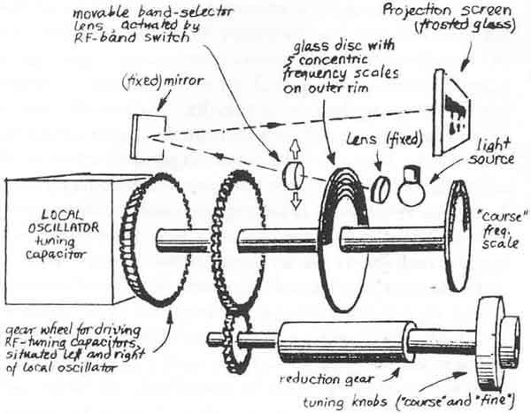
Dolf Prins made the measurements on the E52, shown as Fig. 2-4, and Hans Evers made the sketch of the frequency display system, Fig. 2-2 (RK 78). Richard Walker, G4PRI, is the owner of the spares box, shown in Photo 5. He also made the photo available. The author is grateful to all concerned for their help.
RB
Photo 2 - The mixer and local oscillator tuned circuits. The coils for the low frequency ranges are of the potcore type; the coils for the highest two ranges use ceramic coil formers with burned-on silver windings
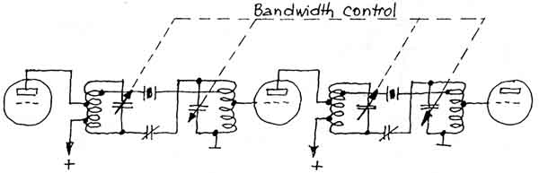
Fig 2-3. Simplified circuit diagram of the IF amplifier, incorporating a crystal filter with continuously variable bandwidth.
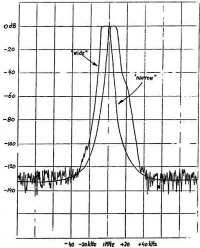
fig 2-4. Measured over-all frequency response of the E52 receiver. The slight asymmetry is probably caused by a detuned fixed filter that precedes the crystal filter. (The receiver had not been realigned since almost half a century before the measurement was made.)
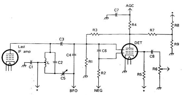
fig 2-5. Simplified circuit diagram for the detector state
Photo 3 - The ten valves can be easily reached by lifting the two lids. One valve has been taken out of its holder to show its size. The push button at the left is for the sensitivity test described in the text. The one just visible at the front makes the crystal-controlled BFO supply calibration signals
Photo 4 - Looking into the compartments of the RF stages. At the extreme left a valveholder can be seen but in the vertical wall there is no hole to insert a valve (photo 3). The holder could contain a neon tube that protects the input circuitry against very strong signals. The facility apparently was only fitted when the receiver was to be used adjacent to transmitters, e.g. on board ships
Photo 5 - Box with spare parts for the receiver type E52b
Photo 6 - Receiver E52b seen from behind. Visible is the vibrator for using the receiver off a 12V DC supply. The small valve that has been removed from its holder is a PTC resistor that forms part of the AGC system
Photo 7 - Owner of the E52b receiver Cas Caspers, PA0CSC, replaces the shielding covers that were removed for photography by the author.
fig 2-6 IF filter circuit (Radcom)