pg 12c. Lorenz Short Wave
Receiver Lo6K39a (=E03237)
The Ultimate Tuned Radio Frequency Set?
by Dick Rollema, PA0SE
[Scanned by LA5FH - not complete] (Lo6K39/Lo6L39 reference
page 24l)
The article is not yet ready because of scanner troubles
In German World War II Radio Equipment (RB65) several aspects of
the construction of these Radios were (discussed and illustrated
by the FUG10 aircraft radio equipment.
We will now have a look at another example: short wave radio
receiver type Lo6K39a, a tuned radio frequency (TRF) set, made by
Lorenz.
XXX
Photo 1a - Lorenz TRF receiver Lo6K39a. The
set belongs to the collection of Mr Cas Caspers, PA0CSC, of
Veldhoven near Eindhoven.
'Lo' stands for 'Lorenz'; '6' means there are six tuned circuits,
'K' means 'Kurzwellen' (short wave), 'L' means Langwellen (long
wave); '39' is the year the set came into operational use and 'a'
means that capacitors of standard types were used.
The German forces used quite a lot of TRF sets, though
superheterodyne receivers with single-knob tuning (ganged
variable capacitors for the input tuned circuits and local
oscillator) were known since about 1932. It is sometimes said
there was fear that radiation from the local oscillator in a
superhet would enable the enemy to locate the set by direction
finders. The German superheterodynes were always very well
screened and featured extensive selectivity before the mixer with
three or more tuned circuits. It is difficult to imagine how the
oscillator signal could reach the antenna via these circuits
which are tuned to a frequency that differs from the oscillator
frequency by the intermediate frequency.
Radiation could just as well be feared for a TRF receiver, which
for telegraphy in the A1A mode (keyed carrier) is operated with
an oscillating detector. True, the amplitude of the signal is
much smaller than of the oscillator signal in a superhet but in
the TRF set the input circuits resonate at the frequency of the
oscillating detector, so transmission of that signal through
these circuits to the antenna is more likely. It has been
reported that a German raider during WWII indeed managed to
locate merchant ships sailing on their own, not in convoy, by
direction finding on the signal radiated by their receivers.
Presumably these ships had rather old-fashioned equipment,
perhaps with an oscillating detector directly coupled to the
antenna.
The German Navy (Kriegsmarine) had another reason to dislike the
superheterodyne receiver: its spurious frequency responses
(second channel or image frequency and higher order products of
the mixing process). On board ship, transmit and receive antennas
are close together. Transmitters may be active with reception on
other frequencies taking place at the same time, so the risk of
spurious responses is a very real one.
The Lo6K39a was not only used on shipboard but was also the main
receiver in the land-based stations that were in contact with the
German submarines.
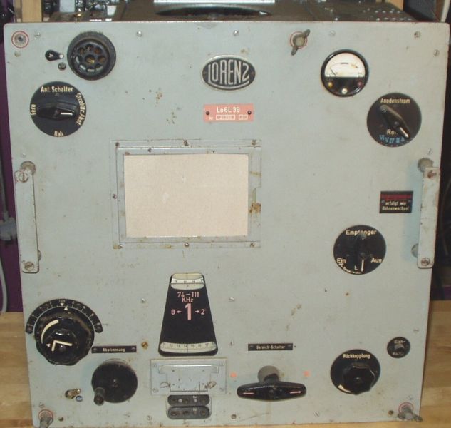
Photo 1b. Lo6L39 = E03750 [75-1500kHz, 6x
RV12P2000, Te30, STV150/20] (LA8AK)
GENERAL DESCRIPTION OF LO6K39A
Lorenz developed the Lo6K39a according to a specification issued
by the Kriegsmarine in 1937. The author had access to the
technical manual for the set and the first line in that
comprehensive booklet neatly summarises what it is. In
translation it says something like 'The shortwave receiver
Lo6K39a is a five valve tuned radio frequency receiver with six
ganged tuning circuits. A sixth valve serves for frequency
calibration'.
Photo 1 shows the front panel of the receiver. The dimensions are
538mm high, 500mm wide and 320mm deep (21.2 x 19.7 x 12.6in
approx.). That is without the shock absorbing feet, on which it
was normally mounted for shipboard use. The radio is built like
the proverbial battleship and that is reflected in its weight, a
solid 65kg (1431b approx.). The radio covers 1.5-25MHz in eight
sub-bands that cover the following ranges according to the
specifications:
| Range 1: 1.50-2.135MHz |
Range 2: 2.135-3.05MHz |
Range 3: 3.05-4.33MHz |
Range 4: 4.33-6.16MHz |
| Range 5: 6.16-8.74MHz |
Range 6: 8.74-12.40MHz |
Range 7: 12.40-17.60MHz |
Range 8: 17.60-25.00MHz |
In practice there is some overlap
between ranges. The relatively small frequency segments of each
range, together with the 50:1 slow-motion drive makes for very
easy tuning, up to the highest frequencies. But it is made even
easier by the outer one of the two concentric knobs to the left
of the dial window, which varies the tuning of the detector
circuit over plus or minus 3kHz around the frequency set by the
main tuning control. The inner knob varies the gain of the
receiver. The main tuning knob is the left-hand one on the bottom
row. The tuned frequency can he read from a separate scale for
each sub-hand. There is no risk of reading the wrong scale
because a window in a mask that rotates with the band selector
control displays only the scale to be used. Below it is a logging
scale and on top a blank scale on which marks can be entered by
pencil through a hole in the glass cover. The mask also clearly
shows the frequency range of the selected sub-band and by means
of arrows even the direction the selector knob has to be turned
for the adjacent subbands. Band switching by means of the crank
on the right of the middle in the bottom row is very positive and
imparts a sturdy feeling, like opening the door of a safe or an
expensive old-time motorcar.
The knob on the extreme right at the bottom controls detector
regeneration. The German designers certainly knew how to make a
superb regeneration control. The detector moves smoothly in or
out of oscillation without any backlash or fringe howl. The round
object at the top left of the front panel covers a neon lamp that
protects the receiver against high voltages on the antenna, e.g.
from a neighbouring transmitter. Immediately below it to the left
is a three-position antenna switch whose function will he
explained later. Top right is a meter with a yellow and a red
pushbutton. Operating the yellow button makes the meter indicate
the 12.6V heater voltage; the needle should be in the yellow
sector of the meter dial. Depressing the red button makes the
meter show the anode DC voltage; the needle should now be in the
red sector of the dial. The knob below the meter allows
measurement of the anode current of each of the six valves; when
currents are normal the needle is in the blue sector of the meter
dial. For this the gain control must be at its maximum position
and the frequency dial at zero on the logging scale (the reason
for this will become clear later).
The meter switch is spring-loaded; when released it automatically
returns to the starting position. The knob in the middle on the
right operates an audio filter, tuned to l000Hz and with a
bandwidth of 200Hz at -3dB. The pushbutton below right activates
a quartz-controlled oscillator for frequency calibration.
Finally below the dial window are outputs for a headphones and an
'Einheitsbetriebsgerät' (Remote control unit).
 |
 |
Fig 1. (The picture is larger than displayed on the screen)
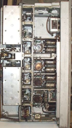
CIRCUIT DESCRIPTION
A simplified circuit diagram is shown in Fig. 1. Reference will
also he made to Photographs 2 and 3 that show the back of the
receiver when taken out of its cabinet. Some of the screening
covers have been removed to show the coil turret and three
sections of the variable capacitor. Inside the receiver a jumper
can be set for either a highimpedance (end fed) antenna or a
low-impedance one (with coaxial feedline).
Switch 4 in Fig. 1 is the antenna switch mentioned before.
Position I is the one normally used for reception. In position II
the input of the receiver is earthed. This permits listening to a
local transmitter without overloading the receiver. Position III
is used to tune a transmitter to the frequency of a station
received. First the receiver is tuned to zero beat with that
station in position I of the switch. Then the switch is moved to
position III. Terminal 'zum Sender' carries a signal at low level
from the transmitter, without any output to the transmit antenna
(silent tuning). The transmitter is then tuned for zero beat in
the receiver. The antenna is followed by a triple tuned bandpass
filter and the first RF valve (1. Vorkreis, 2. Vorkreis,
l.HF-Verst.-Stufe). Neon lamp 5 shunts the first tuned circuit.
The need for it follows from a German specification for all
Kriegsmarine receivers that stated the receiver should be able to
withstand a voltage of 200V RMS at the antenna terminal without
blocking! The first RF valve is followed by a single tuned
filter; the second RF valve (2.HF-Verst.-Stufe), another single
tuned filter and the third RF valve (3.HF-Verst.-Stufe).
The gain of the receiver is controlled by potentiometer 30 that
varies the screen grid voltage of the first two valves. The third
RF valve feeds the signal to the tuned circuit of the leaky grid
detector valve (Audion-Stufe).
The impedance at resonance of a parallel tuned circuit is higher
when the circuit is tuned to the high end of its tuning range
(minimum capacitance) than at the low end. This affects the gain
of the valve that precedes the circuit. That gain is the product
of the mutual conductance (slope) of the valve and the impedance
of the tuned circuit. The net result is that the stage gain
increases when the circuit is tuned from low to high within a
sub-band. As there are three RF valves, each with a tuned circuit
following, the effect is aggravated and it would be necessary to
adjust the gain control continuously when tuning to keep the gain
and signal handling capability the same.
To counter this, the Lorenz engineers used a clever trick. In
photos 2 and 3 a potentiometer can be seen between the two
screening boxes at the right housing the variable capacitor. This
pot is coupled to the shaft of the tuning gang by means of a set
of gears, so it rotates with it. The pot controls the screen-grid
voltage of the third RF valve in such a way that the voltage
becomes lower when the set is tuned towards higher frequencies,
so keeping the gain constant. (The potentiometer is not shown in
the simplified diagram of Fig. 1.)
The detector features the already mentioned smooth regeneration
control through varying its screen-grid voltage by potentiometer
84.
Already mentioned is the fine tuning control that varies the
tuning over ±3kHz around the frequency set by the main control.
The simple solution of a small variable capacitor in parallel
with the main capacitor, as can be found in some receivers for
bandspread, could not he used because the frequency variation by
the fine tuning control would be much higher when the main
capacitor is at its minimum value than at its maximum
capacitance. Instead a coil is used, the inductance of which is
varied by moving a powdered iron core in or out; number 74 in
Fig. 1. This coil is connected to the detector circuit via
another coil per sub-band which is selected such that the desired
frequency range of ±3kHz for the fine tuning control is achieved
for each sub-band.
The coils are housed in a turret with six compartments, each of
which contains eight coil sets, one for each sub-band. Before the
turret rotates the contact fingers on it are lifted. When it has
reached its new position the contact fingers are lowered again. A
separate set of contacts interrupts the anode voltage for the RF
stages and also the headphones are short circuited to avoid
unpleasant crashing sounds when changing hands.
The detector is followed by an audio filter (Tonselektion) with
two circuits tuned to l000Hz that can be switched on by means of
switch 101. The last stage (NF-Versl.-Stufe) is an audio
amplifier that feeds the headphones and/or the
'Einheitsbetriebsgerät' (E.B.G.). That was a remote control unit
that could be placed on, for example, the bridge of the ship.
There was also a version for land-based use.
At the bottom left in Fig. 1 is the calibration oscillator. Its
frequency is determined by quartz crystal 148 on 100kHz. With
antenna switch 4 in position 111 and pushbutton 149 depressed a
signal is heard at every 100kHz division of the frequency scales.
If necessary a correction can be made by a screwdriver
adjustment.
When a valve is changed the new one may have a slightly different
input capacitance that would upset the frequency calibration or
the tracking between the circuits. To counter this, every tuned
circuit that has a valve following not only has the normal
trimmer capacitor for alignment but also a second small one. When
a valve has been replaced this trimmer is used for realignment on
the highest frequency subband and all is well again.
A final remark on the power supply. The manual states that after
some 1000 hours of use the anode voltage may become too low due
to increasing internal resistance with time of the selenium
rectifiers. It is then permitted only once to select a higher
voltage tap on the secondary winding of the power supply
transformer.
The receiver exemplifies several of the features described in
RB65. For instance instead of a chassis a die-cast frame of a
special alloy is used. Also the application of the same type of
valve in all stages: universal pentode RV12P2000, a picture of
which can he seen in RB65 on page 8. The valve goes upside down
into the valve holder that completely surrounds it. In photo 3
the bottoms of four of the valves can be seen through the holes
in the panel on the right.
The coils have small dimensions but a high Q thanks to the use of
powdered iron cores, developed by Hans Vogt.
Lorenz also made a TRF receiver that covered 75-1500kHz: type
Lo6L39 ('L' for long wave). It looks exactly like the Lo6K39a and
is electrically the same as well, apart from the different
frequency range.
SPECIFICATION OF THE LO6K39A
As can be expected from a radio of this high standard the
electrical specification is very complete, although in the days
before WWII some of the electrical characteristics were specified
in a different way from today.
Output is stated as the voltage over a pair of headphones with
5000 ohms impedance at 800Hz. The receiver noise should produce
between 0.2V and 3.0V, with gain control at maximum and the
detector just in oscillation for maximum sensitivity for CW. With
maximum 0.2V receiver noise 2 microvolts input for A1A (CW) and 4
microvolts for A2A (MCW) should produce 1V output at the optimum
position of the regeneration control. According to tests made by
the author, a signal of 0.4-0.8 microvolt EMF from a generator of
50 ohms internal resistance produces a readable CW signal.
One probably wonders what sort of selectivity can be expected
from a TRF set with six tuned circuits. The specs state
selectivity as follows: at ±0.85% detuning a 103 times increase
of signal is required to restore the response from a 2 microvolt
signal at 4.62MHz (signal generator modulated with 400Hz at 30%
modulation depth, mode A2A, regeneration control set just before
onset of oscillation). We would say now that 0.85% detuning
causes 60dB attenuation, which is certainly not bad.
Earlier we mentioned the fear of radiation from the local
oscillator in a superheterodyne or the oscillating detector of a
TRF set. Lo6K39a is also a good design in this respect; Lorenz
states that the voltage at the antenna terminal is at maximum 10
microvolts on 20MHz.
There are many more interesting points in the specs but we will
leave it at that.
LO6K39A IN USE
Several years ago collector Arthur Bauer, PA0AOB, kindly gave the
author a set on loan for evaluation and the help of his
neighbour, a building contractor with bulging muscles, had to be
enlisted to carry the monster (65kg!)-up two flights of stairs to
the shack in the attic. Operating the set fully confirmed what
could be expected from the specification. The set had not been
active for many years. Arthur did not realign the receiver before
it was handed to the author. The only thing he did was to clean
the moving contacts of the coil turret and capacitor gang with
contact spray. Nevertheless the frequency calibration was found
to be remarkably correct. The 100kHz crystal in the calibrator
was spot on.
Tuning was as easy as can be, even single sideband on 21MHz,
thanks to the fine-tuning control. As with most TRF sets the set
is beautifully quiet. The receiver is at its best on CW. Again no
trace of inter- or cross-modulation was found, not even during
night hours in the crowded 40-metre band. And not a single
spurious signal or birdie was observed, quite normal for a TRF
set of course, but it is a reassuring feeling to know that when a
signal is heard one can be sure it is a real one on the frequency
the radio is tuned to.
The author remembers that at the test equipment department of the
electronics firm where he was once employed, a Lo6K39a was used
to check the purity of the output from a signal generator under
test.
ACKNOWLEDGEMENT
The author is grateful to Messrs Cas Caspers, PA0CSC (Photo 4)
and Arthur Bauer, PA0AOB. PA0CSC made his Lo6K39a available for
photography and also loaned the technical manual to the author.
Both PA0AOB and PA0CSC provided extra information, not found in
the manual, and they also checked the manuscript.
RB
XXX
Photo 2 - Removing part of the screening reveals the coil turret.
XXX
Fig. 1 - Simplified circuit diagram of the receiver.
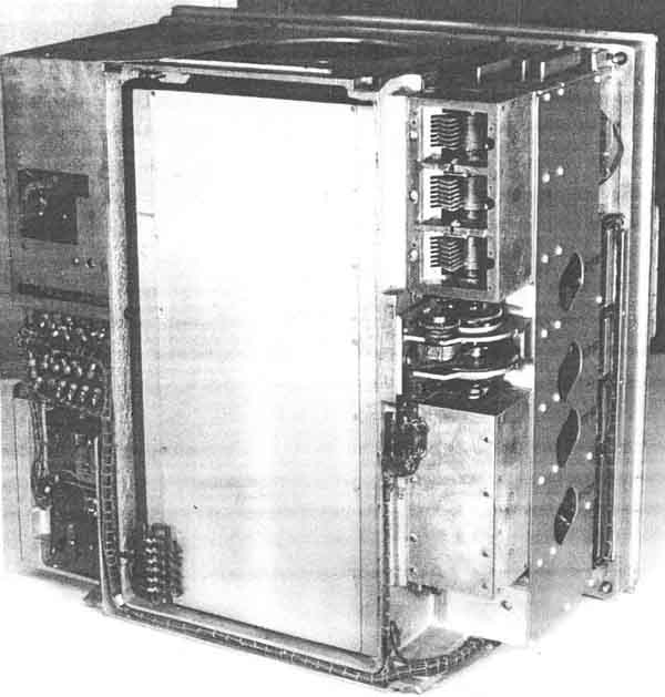
Photo 3a (Lo6K39).
One of the screening boxes has been opened to show three sections
of the six-gang tuning capacitor. Between the boxes can be seen
the potentiometer that keeps the gain constant when tuning over a
frequency sub-band. The pot.meter is driven from the shaft of the
variable capacitor.
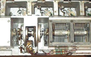
Photo 3b. A closer look at the potmeter for keeping constant gain
over the range (Lo6L39)
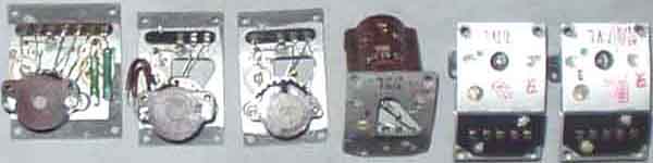
Photo 3c. Some spare coils I got to repair
my rather amateurized Lo6K39 (coil cores
damaged), the problem is very bad sensitivity!
It is better not to adjust than damage, the only German equipment
needing alignment here is when earlier owners were fools.

Fig 4. Owner of the Lo6K39a set described is Mr
Cas Caspers, PA0CSC, seen here typing on a German WWII
Hellschreiber (Feldfernschreiber 24a-32). At the left on the
table is a Telefunken superheterodyne receiver
E52, alsom known as 'Köln', that will be subject of a future
article.
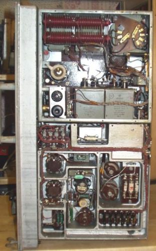
Photo 4. Lo6L39
chassis seen from left (RF and detector stages) and right side
(audio, calibrator and power supply), the STV150/20 voltage
regulator has been substituted for an OA2. It is not known
whether it is possible to spot any differences for the chassises
of Lo6K39 and Lo6L39.
e. German
communication radio - General info
 e/m
e/m
BACK
2004.04.07