
Luft-Boden-Einheitsempfänger
E52 'Köln'
e11
Receiver Intermediate Frequency List, based on info from G3VA and
other sources
e12
Data for German communication receivers
43a
More technical details for E52 receiver
Technical articles under preparation
(received from PA0SE Dick Rollema):
10a Introduction to German World War II Radio Equipment
12a. German World War
II Radio Equipment - Köln E52 receiver - part 1
(PA0SE Dick Rolema)
12b. German World War II Radio Equipment - Köln
E52 receiver - part 2 (PA0SE Dick Rolema)
12c. Lorenz Shortwave Receiver Lo6K39a
(Lo6L39), The ultimate TRF set [PA0SE]
12d. Telefunken World War II Superheterodyne Receiver Kw.E.a
(Lw.E.a) [PA0SE]
10b. Telefunken World War II Universal TRF receiver Torn.E.b
[PA0SE]
This receiver is also mentioned by G3VA in Radcom,
Technical topics, November 2004, and Januar 2005 ++
*** Note: Anlagen - Kennblatt is
available, but it is 7 pages in jpg and makes an email of
3500kbytes for T8K44/E52, 10 pages = 5000kB for T9K39
All editing I have done is to increase
contrast and remove some rubbish. So please send an email if you
want some of the files.
Hope to scan to text later. They
are relatively bad quality, particularly that for T8K44.
My receiver has been borrowed by a
mate and it is not possible to show other pictures than parts
which were
radio amateur'ized in 59. On the other hand I was told that my
E52 a 30 years old bad reputation among the
lids because the oscillator valve needed to be changed ever so
often, the fault was soon traced to be defective
grid leak, and I am shocked when considering that nobody - even
when I know some of them were electronic
engineers - checked so much as to measure grid leak of "an
ackward valve stage".
Frequency ranges:
1480-3020kHz (White)
2980-6040 (Red)
5975-10050 (Yel)
9950-17700 (Blue)
17600-25200kHz (Grn)
Another reference says: Frequency 1,6-2,9 3,2-5,8 6,5-9,7
10,6-17,0 18,6-24,2MHz
10x RV12P2000, 2x RG12D60, STV140/60, Urfa 610, 2x OB120/4 (dial
lamps).
Circuit: RF, RF, MIX, LO, IF, IF, IF, Det/Audio, Audio
output, BFO
IF= 1MHz, 2x xtal filter and 6. order IF LC-filter,
bandwidth 0.2-5kHz continously variable
Sensitivity: To obtain an output voltage of 5V on
headphones (4k ohm) with 30% noise voltage are with the following
modes and ranges the following RF voltage is needed.
Ranges I II III IV V
A1 narrow 0,5µV 0,5µV 0,5µV 0,5µV 0,5µV
A3 narrow *) 5µV 6-5µV 6-3µV 7-5µV 7-14µV
A3 wide **) 3µV 3µV 3µV 4-3µV 5-4µV
*) 400Hz antenna, **) 400Hz cable
Image rejection:
25MHz: 86dB, 19MHz: 94dB. For the ranges I...IV the figures
are even better.
Selectivity:
Selectivity control Wide (5kHz) Narrow (200Hz)
Offset frequency +5.25 +12 +15 +0.2 +1 +2
Attenuation: 3dB 40dB 60dB 3dB 40dB 60dB
Audio output impedance: 4000 ohm
Measures: 245H x 446W x 350mm Deep
Weight: 40.8kg.
Power: 110V, 155V, 190V, 210V, 220V or 230V AC 50W, 12V
(11-14.5V) DC 75W
Accessories:
DF- unit, FuPeil A70k*
ISB-unit (Seitenband-Auswählgerät).
Note:
While the circuit diagram for E52b says that this may be a
simplified version of the
E52a, it seems not to be always true. All units seem to be equal
for most series of this receiver.
What is simplified is the circuit diagram. Although it is not
shown you may find that the
audio stage has audio-noise-limiter, resistors and switches for
valve testers are included.
Remote Control may still work. So you really need the circuit
diagram for E52a to
understand the possibilities of your E52b (and to repair it).
Further information: Telefunken-Zeitung Heft 90, März 1951:
Kurzwellenempfänger
Funkschau 1979, Heft 1, Nachrichtentecknik; Abgleich eines
regelbaren Doppelquarzfilters
Radio och Television Nr. 8 1980 pp17; Tysk 40-tals radioklenod.
Siemens & Halske: Seitenband-Auswählgerät EB1/3a 9Funk
üstr 144K1 (Independent Sideband)
Anlagen-Kennblatt Nr. A203 Ûberlagerungsempfänger T8K44 (Köln)
- Krigesmarine
*) See "Die deutschen Funkpeil- und Horch-verfahren bis
1945" (F.Trenkle) pp145, this unit has LV1 valve .
Block circuit for E52-series receivers, note that
first stage is the DF-unit and it is not covered by
the main circuit diagram. See KW-Fernpeilanlage Fu Peil A70k (V1=LV1), simplified
circuit diagram
on pg 145, "Die Deutschen Funkpeil- und -Horchverfahren bis
1945" (Fritz Trenkle).
Independent Sideband
Adapter for E52b
Similar units are supposed to have been used
since 1940, but this is the only reference SM5AIC could find.
This adapter was originally designed in 1944 for FuHEc (1875kHz
IF), see info on page 22i
The equipment is mentioned by Fritz Trenkle:
Die dt. Funkpeil- und -Horch-Verfahren bis 1945, S.35.
External connections planned for the
series of receivers, based on reading the different
available circuit diagrams for these receivers
Krachtöter = ANL (audio noise limiter), NF = AF,
ZF = IF, Samlerbetrieb = battery operated, MEFA = diversity, NF
Pegel = audio level.
E52 detectors and audio amplifier
See the notes for Mw.E.c for application of
RV12P2000 as detector on pg
43a. Here the
'anode' is used in to delay the AGC such
that a certain amount of detected voltage must be present before
it is some variation in voltage to AGC-Line. For Kw.E.a the
AGC-detector diodes are biassed with +4V, but it is not possible
here as the cathode is grounded. In Lorenz 6P203 the cathode
(EBC91/6AV6) has +5,5v level and gives a similar delay.
Note that AF gain control is bypassed for A1A
reception. This is not practical for amateur radio (SSB), but may
easily be changed.
It should be considered that the German WWII operator needed easy
as possible operation which suited his often limited experience
with radio equipment. You'll find similar mode switch in Mw.E.c
and Kw:E.a. For SSB reception it is impossible not having the
possibility to decrease the RF gain (to avoid overloading the
detector) at the same time as you increase AF gain (since the
level
from the detector has been reduced far below normal).
 |
 |
 |
 |
 |
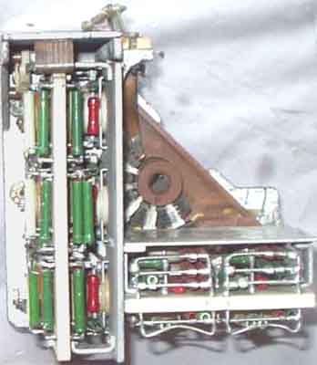 |
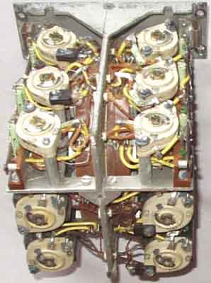
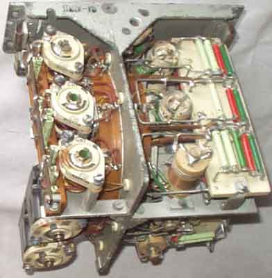
Some radio-amateurized E52 coil
units. RF unit (input coils) to the left, oscillator
coils to the right. Note the
temperature
compensation capacitor block. "Fortunately" the cores
are only accessible through a hole in the trimming capacitors and
the fools
may not discover them, and as such don't damage when they perform
their unneccessary alignment without proper tools
 |
 |
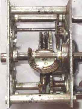 |
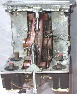
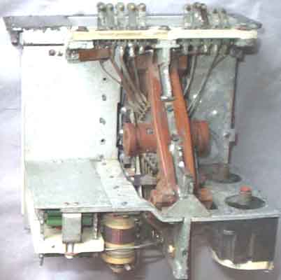
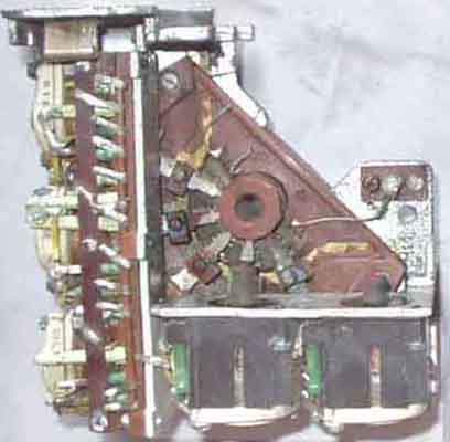
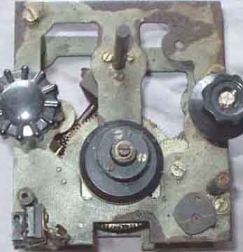
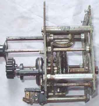
E52 (Köln) tuning drive mechanism
All these units comes from a radio amateur, who discarded
this receiver in 1959 because the drive was stuck, but
I managed to release it 30 years later using hydrocloric acid
(HCl). Be sure to wash it thoroughly after and dry it, before you
add oil and grease!
Shouldn't mention that the lid ran a radio/TV-repair shop, a
really QSD.....
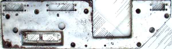
Backplate, 41x12cm (E52 Köln)
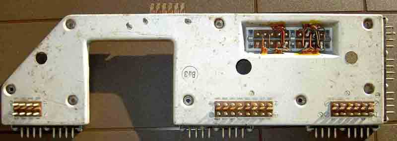
The proper backplate (tnx Carsten Falk DL1LAY)
Available
E52 handbook:
At last - a very good book
available from Werner Gierlach DL6VW; 92 pages
with circuit diagrams,
figures, fotos and text to explain how to deal with the receiver
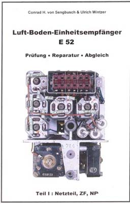
If you are a serious E52 'Köln' collector who
wish to have the receiver in best working condx,
you just can't do without it. Most of us have equipment which are
damaged by the fools who thought
it needed trimming, or thought that it is better to trim it even
if you destroy it with improper tools,
then you need this book to repair what can be done, see more
detailed info on page e73.
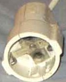
Mains connector, see page 11d
SSB reception with E52b.
The BFO is normally xtal controlled and it seems to work for USB.
But it is already in some BFO-units provision to short the xtal
and operate as variable BFO (C240 =6,5pF), these are original
units for E52-a. It seems that my E52-b has been modified and I
am not really sure what was in the first place. Since it has been
used by radio amateurs who are not very ingenious (they never
understood that a resistor was defective), it was probably a very
easy modification.
Somewhat simplified BFO for the E52-b
See the following articles in Radcom:
Radcom Nov80 pp1157. TT Constant-k crystal filters in Mw.E.c and
E52
CQ-DL Mar. 85 pp138-140 was an article about MwEc xtal filter by
DL9LX Ulrich Fleischmann
Radcom Jun85, TT: TTS pp34-35: Constant-k crystal filters (Mw.E.c
+ Köln E52) PA0SE
Radcom 11/1987 TT Military equipment, German wartime pp 202
(FuG10)
Radcom 1994/12 pp60-61 Military and clandestine radios of WW2,
HRO Senior
Radcom 1997/11 pp65-66 Regenerative straight receivers, Ha5K39,
Paraset MK VII/7
Radcom 1999/09 -pp53-54 The Not-Invented-Here-Dyndrome, SE108/10,
Ha5K39, Köln E52, Mw.E.c
Radcom 1999/11 -pp64 Pentodes as double-diode-triodes, RV12P2000,
EF91/6AM6, EBC90
Radcom 2000/01 -pp56-57 The Köln E52 IF xtal filter (Mw.E.c),
DJ6EV
Radcom 2000/05 -pp55-56 Ressurgence of Hellschreiber. New HF
digital modes
Stikkord: Funkpeiler, radiopeile mottakeren Køln E52a, mottaker Køln E52b (i Telemark kallt Kølen etter fjell i Sverige), SSB-tilsats, ISB Adapter
Last update: 2004.10.16