
Jan Martin Nöding
g32. BC receiver techniques,
accessories and audio.
Links to other
pages:
c. Amateur
radio experiments
e13.
Receiver's IF frequency list II
f.
Boatanchors and information
L. VLF, MF
and 136kHz equipment and antennas
m.
Measuring instruments and tools
g31 various notes for BC-receivers
g33.
Volksempfänger, UKW1c, DAH50 valve application
g41.
Synchronous AM detectors
g11
Tandberg Huldra 4
Contents on this
page:
low voltage operation for normal valves, RIAA,
crystal set, Q-multiplier
 |
 |
 |
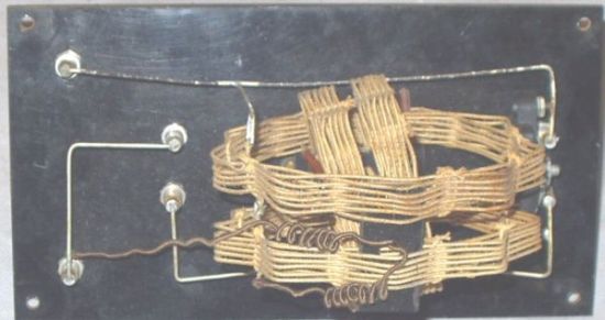
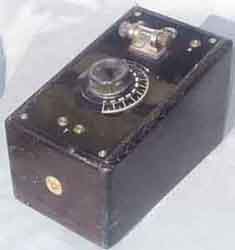
Medium wave crystal set made by A. Thunell,
Borlänge, Sweden
 |
 |
The Crystal Set seen from below - it is not much here! A variable
coil (43,7-140µH) and a 2000cm (2,2nF) decoupling capacitor to
the right.
Circuit diagram for the crystal set, just three components.
(A. Thunell, Borlänge)
More or less hidden features for BC-receivers.
 |
 |
The hidden
Q-multiplier. Some pieces of
equipment have obscure details which solved the problem on the
production line or is just a hidden improvement.
Later versions of Radionette Kurér portable
receivers (DK96/1AB6, DF96/1AJ4, DAF96/1AH5, DL96/3C4) have
positive feedback in the IF, no notice has been found in any of
the circuit diagrams, they are available at www.nrhf.no.
The drawing shows how to find the modification, in my receiver
the thin wire was covered with red pvc instead of blue as for
Stein Torp.
The original circuit shows no feedback. The +85side of the second IF transformer (coil
MFC of transformer 2014A) goes via a one turn link on to the
first IF transformer (coil MFB of transformer 2269) to +85v. The
IF transformers are probably of English manufacture (Salford
Electrical Instruments Ltd) and have very high Q (at least Q=200)
compared to standard types, see the note below.
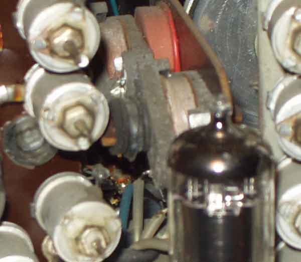
The actual receiver with the feedback winding visible as a red
covered wire around the inner coil of the IF coil (behind DF96
IF-amplifier valve). Component values: .039=39k, .25=250nF.
This receiver has s/n: 688 539. Have also an older model receiver
with DK92/1AC6 mixer valve, s/n 388 901, but it hasn't this
modification.
The not-so-hidden-circuit (Q-multiplier) and other
applications.
On the other hand, Stein Torp (LA7MI) notes that a similar
circuit is documented for Radionette 'Menuett' model 1954 (S/N
above nr 497 001) [NRHF cct 54RN1S 8-89 - either versions]. The
circuit diagram shows a second link from anode circuit of the IF
amplifier (EBF80/6N8) on to the first IF transformer (T216) while
output from the EBF80 amplifier goes to T217. Some improved
selectivity seems to have been an advantage, but it is later
abandomed, when the main feature is FM reception while AM is more
or less forgotten.
Component values: .022=22K, .22=220k, 4.7=4,7M, .04 = 40nF,
200=200pF
David Andersen type 561 (562)
portable radios (dated 1956).
In this receiver's IF amplifier is used the more modern valve
DF97 (1AN5) with available suppressor grid connection. The
positive feedback is put back into the suppressor grid instead of
control grid.
More applications with positive IF feedback.
Q-multipliers have been used in many receivers where the
selectivity of early models might have shown some room for
improvement. Telefunken Spez. 801 from 1936, were modified after
a year or two to include a multiplier, possibly based on
published circuit from ARRL handbook, see page
17t. He also mentions that more or less invisible
Q-multipliers may have been more widely applied than we would
first believe. Max Funke "Mikrohet" receiver from 1961
has a positive feedback to improve the ECC85/6AQ8 mixer, and we
found FM-tuners using ECC85 which have positive feedback (neutralizing)
for 10,7MHz to improve the Q-factor and stability.
FM-tuner with 'hidden' 10.7MHz IF feedback (ref.
Q-multiplier technique). The degree of positive feedback is
decided by the 1000pF capacitor at lower left, it is not much
impedance (-j16 on 10.7MHz). Some Tandberg tuners use smaller
capacitors, but it is difficult to compare. The 15pF decoupling
is a part of a capacitive bridge to minimize oscillator
radiation. Coil 442 is for radio frequency, 441 is a link on 440.
which is the local oscillator. 426 is first 10,7MHz IF
transformer. <Radionette Kvartett Hi-Fi S/N 93 0001 up. NRHF
Sheet 60RN1S> Valve: ECC85/6AQ8. 0.22=220kW
In FM tuners (with BF200 and 2x BF195) for Radionette and
Tandberg products from around 1971 it is a notch-circuit
(C119/L103) between emitter/base of the mixer transistor, it is
probably tuned to 10,7MHz to provide proper termination
(short-circuit) on the input port for all other frequencies than
the RF and LO. According the circuit diagram for these two makes
the same FM tuner is used.
High-Q coils for 455kHz IF
transformers.
Stein Torp (LA7MI) mentions that Radionette used specially high-Q
circuits for the first 455kHz IF coils. While normal Q-values
found in transformers from Torotor and Philips are 100-110, the
coils used in Radionette models between 1939-1955 (no exact info
available) have a Q value around 200. This means 6dB higher gain
and better selectivity. The coils were made at Salford Electrical
Instruments Ltd, England, and he once received an offer from this
factory for a planned homebrew receiver.
See also applications by Edda Radiofabrik and Østfold Radio
(Mascot).

Find
data for RV12P2000 (and other valve types)
Q multiplier shown in ARRL handbook 1939
 |
 |
Q-multiplier using 12AT7/ECC81
(or almost any twin triode)
Q-multiplier using BF245
RIAA amplifier for using record player with modern
stereo equipment.
The problem today is that you wish to play your own
records, but the music box has only line input and it doesn't
match the lines from the record player, so you need a special
characteristique amplifier. I checked the circuit diagram for
Tandberg Huldra 9 - not sure why it is so famous, but it has a
good reputation, so I just relied upon it. I chose discrete
devices since they are easier for dead-bug construction. The
amplifier shown is for one channel, so you need two amplifiers,
one for left and another for right channel. Either uses the same
supply wires, and the first two transistors in either amplifier
are decoupled with the same 100µF capacitor (and 2k7=2.7kW resistor) and the output stages to +24V
with the same 22µF capacitor. Use a supply which is not
regulated, it is only a transformer, rectifier bridge and
electrolytic capacitor, but it is no hum problems, so
common-mode-rejection seems to be good. (2004.01.09)
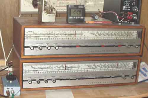
Tandberg Huldra 9 with remote control for the mediumwave
frame antenna seen on lower left side,
more info on page L2. Modifications on my BC-receivers are
only on the rear side.
Application of EF39/6K7 and
RV12P2000 on low supply voltage. The gain is vastly
improved when suppressor grid is connected to +B. It seems not to
be a good idea to try triode-connection.
 |
 |
 |
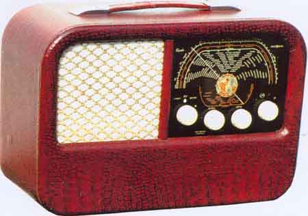
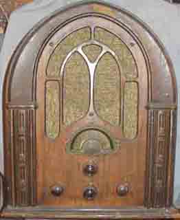
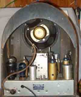
Atwater Kent model 137P BC-radio receiver.
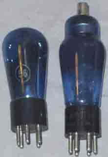
Note that 3 valves (out of 7) - type 56 and 58 - have blue coloured glass for some reason or
other (not every 58 in this receiver are blue).
Simplified circuit diagram for Tandberg Huldra 4
Zwischenbasis amplifier using
1/2-ECC85(6AQ8) in Philips B4N93A from 1959. Although this
amplfier is wellknown from mid-50's, it is not used by all
manufacturers. The advantage of this VHF amplifier is that
minimum noisefigure and maximum gain can be achieved
simultaneously. Note the neutralizing capacitor C2. Reference page g34.
About trimming of BC-receivers in
the shortwave range.........
LA7MI mentions that they had a Radionette Symfoni 3D (= Studio
3D) BC receiver at home back in the 50's. The calibration was
correct in the ends of the highest shortwave band (11-22Mc/s),
but not at all in between. He borrowed a signal generator and
discovered that the receiver was tuned with signal frequency
below local oscillator in the upper end, but above it on the
lower end. The attenuation of mirror frequency wasn't
particularly good on the shortwave band. He removed some beewax
and got the receiver trimmed more properly, and the alignment
seemed to be much better over the band.
topcaps2.jpg
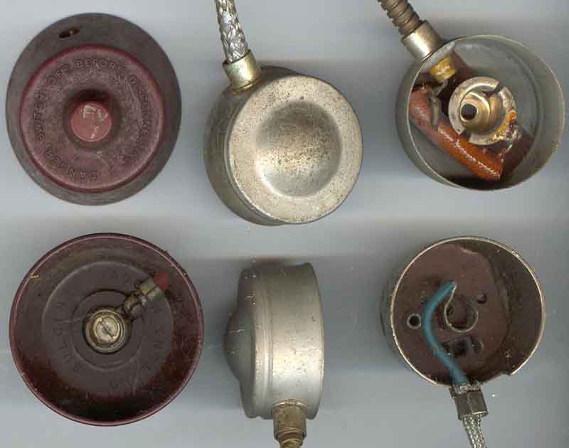
topcaps
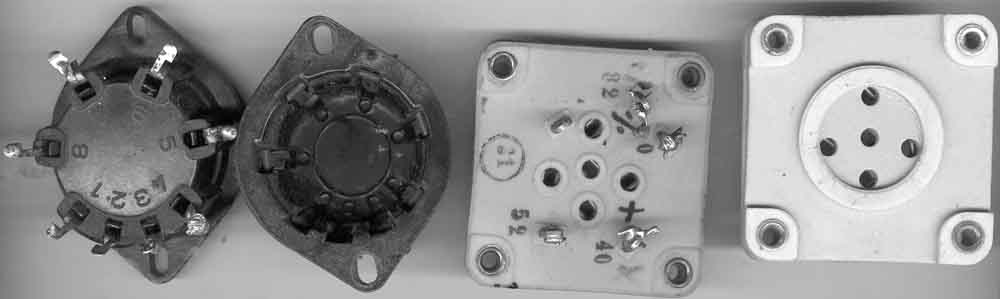
sockets from 1930's
Husk at blyholdig-loddetinn blir forbudt å selge efter
gjeldende EU direktiv
fra 1/7-2006, antakeligvis blir ikke lagrene fornyet i særlig
grad slik at
man kan få problemer å anskaffe seg slikt i tiden fremover
Component sources to repair
boatanchors:
Radiomuseet.se/butik (Gøteborg)
Norsk
Radiohistorisk forening (Christiania)
To avoid having too large page,
the following topics are moved to new pages:
g33.
Volksempfänger, UKW1c, DAH50 valve application
g41.
Synchronous AM detectors
2004.12.29
