
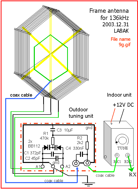
L2. Antennas for VLF and 136kHz reception
Related links:
 L1. VLF technik (RX)
L90.Suggested conventional TX
VFO for 136kHz
M . Electronic measuring
instruments
1)
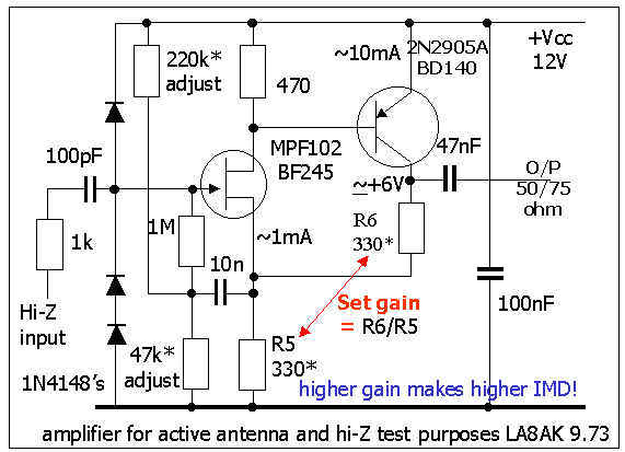
A high-input impedance amplifier for uncritical
applications (suggested by LA7MI in
1973). May well be used for a tuned frame aerial, but not for a
broadband type active aerial.
It has gain, but you should be careful to adjust it too high, and
the positive feedback to the
gate circuit should be used with care, or avoided if possible.
I used it for active antenna and tuned frame aerial covering
500-4000kHz in 1973-1985,
also used in many measuring instruments.It is normally flat up to
above 10-15MHz,
the lower limit depends on the capacitor valuess. It was some
problems with the local mediumwave
radio "Stavanger krinkaster" which was not too far
away.
2)
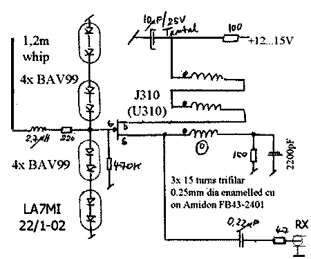
Active antenna and VLF preamplifier
My latest active aerial is based on LA7MI's
construction, too. Here is his circuit for 0.01-40MHz.
It has almost the same gain as mine, but with 47ohm output
resistor the gain drops to 0.3x.
The effect of the 2200pF bypass capacitor in the source circuit
is to reduce gain on lower frequencies.
The small coil on the input forms a lowpassfilter
to attenuate 90-100MHz broadcast transmitters.
Frequency response is flat up to 50 MHz. IP3
on the output is over + 30 dBm..
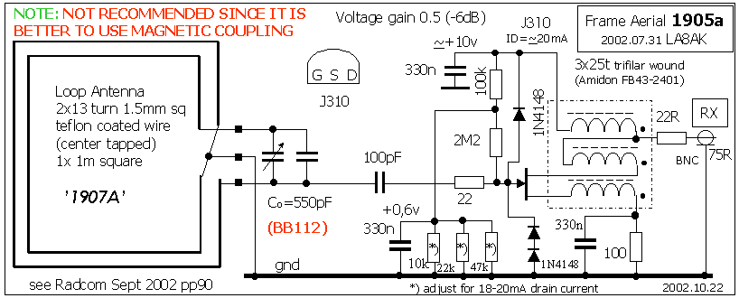
3) Suggested active aerial (VLF preamplifier) using the
valve E280F
Suggested high input impedance amplifier as active aerial using
thermionic valve - a circuit meant
for our boatanchor friends. The suggestion is based on experience
with J310, a pentode may
be easier to use than triodes, since forward conductance is
higher for the same anode current. Data for
some types (C3g, E83F, E180F and E280F) were
checked. It was easier to find the neccessary
data
for E280F, see Frank's site for
datasheet. It may according to the data sheet operate with
relatively
high forward conductance even on +110V, but I didn't recalculate
the figures for this supply voltage.
The forward conductance should be at least 15mmho (15mA/V) and
the grid bias shouldn't be too low,
as only 1V seem to cause problems in certain equipment. So it is
better to increase the screen voltage,
to choose higher grid bias voltage for the same gm and anode current.
It is important to use the large enough toroid core for winding
with pvc-coated wire for sufficient insulation
between the windings and to the core. Normally mentioned Amidon
cores seem too to have small inner
diameter. Spurious killer resistor - at least in the in anode
circuit seems important to remember.
It seems to be some interest for this construction, and it is
copied to another site.
One advantage is that input overvoltage protection is not really
necessary - at least not for
anything but direct lightening stroke. It was suggested for the
boatanchor fraternity, but it
seems to be some other part, possibly BC-DX'ing?.
Suggested transformer which is tested to withstand 20kV spark
pulses and DC. Ferrite core: Siemens B64290-K618-X27 25mm OD.
Here is shown 5x 10turns with pvc mounting wire and in 75 ohm
application a winding has a minimum frequency limit of ca. 5kHz
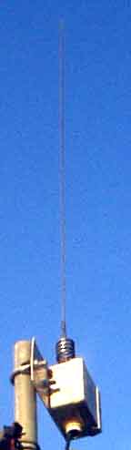
4a) Remote fed VLF active aerial
 |
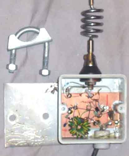 |
Active aerial amplifier with J310 (1) mounted in a Hensel
D9025 plastic box for
electrical installations
(84x84x52mm outer dimensions w/lid). Whip is a
5/8l 2m mobile whip, the length is not
important at all. The
best reason for using the whip is that it is waterproof.
Otherwise all connections should have been in the bottom.
See RPB 182 "Aktive Antennen
für DX-Empfang" (ISBN 3-7723-1821-5) for
more ideas of how to improve
the antenna element dependent on coverage. The box was opened (in
december 2003) after almost two years,
and was dry inside in spite that no precautions has been taken,
and it has not been used for some time.
Between the alu-plate and box is filled with tectyl bodysafe to
secure against water protruding along the screws.
It was soon discovered the importance of adding a 3mm red LED (with 4k7
resistor for just 2mA current) in
the lower side of the box to indicate that it is in operation.
Had some problem with water going into and
damaging a BNC connector halftway to the shack. Solved it with a
coke-bottle.
The active antenna has been used to listen to the Alexanderson
alternator on 17.2kHz, see the notes on page M2
for modification of the Siemens D2006 level meter to adjust the
pitch with 80Hz bandwidth to listen to cw signals
4B
 |
 |
The active aerial should be placed above the roof and it is a
good idea to use a choke type balun on the
coax cable at a weather protected place before it enters to house
to avoid noise fields from the house.
See Guide to EMC, G3JWI, RSGB. In this situation it may sometime
be important to cope with noise
sources and harmonics down below 10kHz so you should use a high
permeability core. Combination of
two cores may also improve the spectre. Use of a core from an old
TV's horisontal output stage seems to
be a good idea. In some extraordinary cases with long feed-line
the use the core from a mains or audio
transformer for the second choke balun may help.
4C.
 |
 |
 |
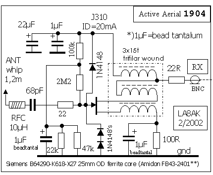
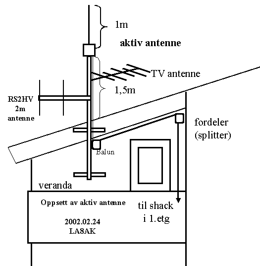
OUTDOOR ACTIVE ANTENNA.
This is the recommended active aerial with
preamplifier using J310 or P8002 FET, the
preamplifier has also been used with a frame aerial,
but it was later discovered that a frame aerial for 136kHz band
didn't need amplification. Using the transformer the so-called
"current gain" is
increased by a factor of 3, meaning that output impedance is
lower than for a simple source follower, but still the overall
voltage gain is only 0.5x (minus six dB).
It is connected a 10MW resistor from
the antenna whip to ground to decharge static voltage, and the
LED with 4k7
resistor is also missed on the circuit diagram, it is quite
useful to have an optical indication that it is in operation.
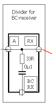
DIVIDER.
A divider has been installed along the cable for signal
to the BC-receiver in first floor. The connection for BC
receiver could well be looser, since BBC Radio 4 on 199kHz is
still incredible 0.5mV, so it is not the signal
strength which limits the reception at Norwegian south coast!
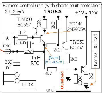
REMOTE POWER FEED & CONTROL UNIT (in ground floor).
Have added some monitoring circuit to see that the amplifier
draws current, but not shortcircuit the cable, it has been
changed many times and I am not quite sure about the actual
status.
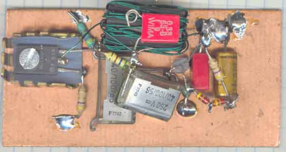
Remote power feed unit for active VLF antenna:
It is shown how the components are thrown into the box
5)
 |
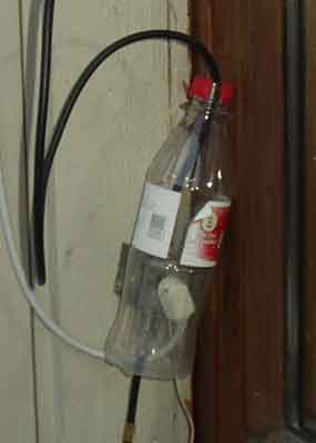 |
Installing the active antenna above the roof -
above everything else in a little mast for TV and 2m FM antennas.
A half litre bottle reduces rain water on the splitter and
connectors.
Note: A loop is usually better than an active antenna, an active
antenna is a compromise when a loop is not possible to use or to
cover larger frequency range.
6) Another (NOT recommended)
frame antenna for 136kHz,
shown only for comparison
The first working version for 136kHz, it
has corrugated electrical plastic tube as for the 80m version,
and was
covered with aliminium shield (paper) - when I still believed in
the myth of loops and electrical noise problem.
Later I learned that there
are many illusions to fight. It is - at least - mine and others
experience that the magnetic loop has not problem with electrical
noise, not even an un-screened loop.
Used 0.25mm wire, but the antenna seemed so
interesting that it was a challenge to investigate further.
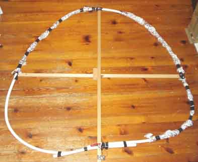
| Some frame antenna
constructions were described in magazines and used
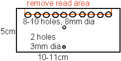
telephone cable for an easy construction of a multi-turn frame, the other advantage was the screen/braid. My success in this matter was very poor, and it was soon discovered that the winding capacitance was rather high. Typical cable constants gives a capacitance of 50nF/km, so a 50m loop wire is still 2500pF, another history is that the wire diameter is seldom larger than 0.4-0.6mm and as such ohmic losses are quite high. It can be calculated using MathCad that Q decreases dramatically when the winding capacity is high, and in my case it was hardly possible to measure any deflection on the Radiometer QM1 meter at all, some sort of deflection could be found for reactance value - possibly inductance, but it was soon understood that good antennas don't come that easy. |
This is the first working version of frame antenna for 136kHz
using the preamplifier described above. The
antenna winding is center-tapped and grounded.
It was later experienced that the signal level is somewhat high,
but the signal-to-noise is degraded, and it is only waste of
ressources and time to use this
extra preamplifier. It will only produce extra noise and limit
the dynamic range for the receiver as signal strength is so high
without the amplifier that you can
hear a distinct increase in the noise when the antenna is tuned.
7)
Ruse type frame antenna
.gif)
Another idea we discussed - to screen the loop antenna without
increasing the capacitance a lot is to use a Ruse
type of screen. Since the holes could be rather large and still
effective for the long wavelength, chicken mesh is
probably far better than needed. I was told by Knut N. Stokke
that it was already a Frenchman (Ruse) who had
proposed this sort of screen, which reminds me of a fishing tool
for catching lobsters. The center should be
grounded as above. The open section (break) is where it is most
practical, on the top or in the bottom, perhaps
the top is most practical since ground is available in the
bottom.
Based on later experience it is probably important to ground the
center of the winding to reduce influence from
nearby noise fields.
8) Magnetic loops for LF and HF reception
 |
 |
1) 80m (160m) frame aerial (60x60cm) , see
details on page a1. The later 136kHz aerial
is based on results with this aerial.
2) One of the first versions of LF-frame antenna had an
amplifier, but it was found not needed for other purposes than
keeping
sufficient heat to avoid damp inside the box, so it was abandomed
with good result. The passive version has high enough output
signal, in fact far above the receiver's noise floor. The
coupling loop is marked with red line. Tried to minimize the
winding
capacitance by spreading the wire so wires follows different
routes, but it was experienced that it would have been a better
idea if it was shaped as the drawing below
9a)
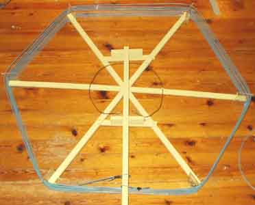
LF Frame aerial system - overall view. The
Q-value is important, and this is improved
when the winding is broader and the turns are spaced.as shown
(but was discovered after
the antenna was built and mounted in the garden). It may have
some effect to use choke type balun
to avoid coupling noise sources in the house on to the aerial,
see above, but it has not been experienced
any such problems here.
It should be noted that all
connections should be made on the lower side of the box.
Using a Hensel
D9015 as for the active antenna seems to be a
very good choice. I've used banana plugs for the 3 wires
going to the main loop and a coax connector for the coupling
loop. A plastic box for food was used as an
emergency, and should be covered by a plastic bag from the top to
avoid water from protruding into it.
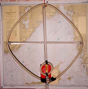
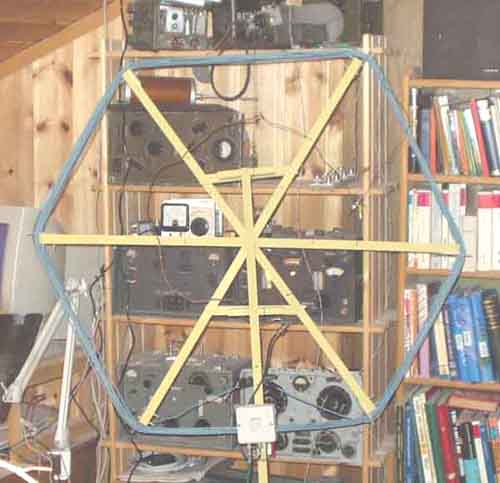
9b) The recommended
FRAME-ANTENNA or Magnetic Loop for LF reception
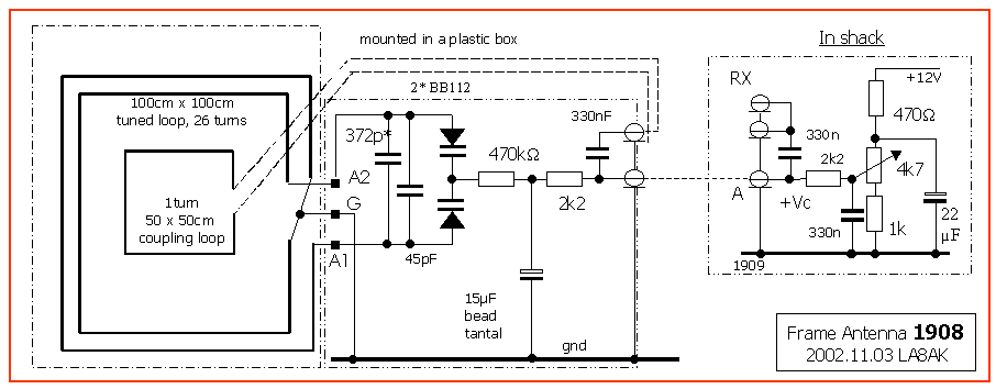
Frame aerial for 136kHz reception. This is the
last version, it was a problem to find a suitable value
for the fixed capacitors, because it is much variation between
hot and cold, dry and wet conditions,
or when it is covered by wet snow or ice. When tuned to 136kHz
the beacon on 138.8 is attenuated
almost 30dB, so remote tuning is a must, I may have lost many
signals before I discovered this effect.
Made a frame aerial for 80/160m and discovered then that it was
no need for an aerial-amplifier, although
somebody seems to believe it and waste ressources on it. I
discovered that, with decent tuning capacitance,
the coupling loop shall have an area of 1/100 frame total area.
You get it with a 1m diameter frame and 25 turns,
and a loop of half this diameter, or single turn frame for HF
with a coupling look of 1/10 frame diameter.
The 80m frame was used when electric noise from powerline was a
problem, later the powerlines were
modernized and the loop wasn't needed any more.
Tuning capacitance for 136kHz is 550pF, but may vary for the
different constructions.
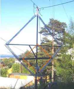
10a) More about frame-antenna
construction (magnetic loop).
Just had started to test the 136kHz frame when Stein, LA7MI sent
me a copy of the article from
Electronics World Aug. 2002 (unknown author), and I learned that
my mechanical design wasn't optimum.
First wished to see how my construction worked out, and apart
from some self capacitance and detuning
by rain and snow it is quite succesful. On the other hand, I have
now changed the concept - as seen below.
 |
 |
 |
1,2) Plastic stand-off insulators for the improved frame antenna,
made from acrylic plastic (perspex).
They are delivered with protective white PVC, and couldn't be
seen on the picture when this is removed.
3) Construction of the new frame antenna (magnetic loop). I
overlooked the obvious reasons why the
frame was oriented as shown in Electronics World Aug. 2002, my
previous drawings shows how I thought
it could have been, but overlooked that the lowest spreader
cannot be on along the support rod,
but had to be to the side of it.
10b) Magnetic loop antenna for MW
reception
 |
 Remote control unit shown at lower left of the Tandberg Huldra 9's |
Still a lot of snow outside, so it had to be an indoor picture
(without the coca cola bottle installed)...
The frame.
The antenna shown above, with 8 turns (1m dia) has an
inductance of 140µH measured with Radiometer MM1f,
and 130µH when measured with Impedance Meter 252. With a typical
300+400pF BC-type capacitor it
covers only 700-1500kHz (possibly reduced coverage because of
coil self capacitance), but with the circuit shown
below using BB130 capacitance diodes (in anti-paralell
arrangement) the coverage is far more than the mediumwave
band, but has not been checked how much it covers. The coupling
loop was increased to 50cm diameter, but
still it tunes rather sharp.
 |
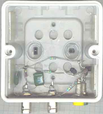 |
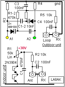
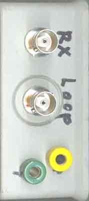 |
Remote tuning and construction of outdoor
unit.
Suggested remote tuning circuit for larger capacitance swing,
+2...30V voltage variation. A tinned iron plate
is mounted and fixed with the BNC connectors for a solderable
ground plane. It might be an advantage to
cover it with vaseline oil to prevent rust when the components
are soldered to ground. It is not much else inside
the Hensel 9025 plastic box (84x84x52mm outer
dimensions w/lid). The remote control is somewhat similar to
that described in 9B, but I chose BB130
30V varicap diodes instead of 12V (BB112) for possible
better immunity.
R1=R2=220k, but not supposed to be critical
Indoor remote control box.
It seems to be no problem to use a standard linear pot.meter with
normal 5cm (2 in) diameter knob for the
frequency tuning. No particular rules were followed. Two
E-B-diodes were used to stabilize minimum voltage,
perhaps not worth it, but I wished to see how it worked.
Frame center ground.
In the first place I thought that noise couldn't be a problem
with a magnetic antenna, and didn't use the centertap
on the main frame, but experienced bad hum pick-up modulating the
signals as the tuning was peaked.
The problem dissappeared with the center ground connected.
Resistors R3 and R4 (220k) are therefore not
needed any more. A half Cola bottle may be put over the plastic
box for weatherproofing the connections
underneath, remember that it is usually not as long as you think,
so cut it a little longer, usually a 5cm frame
beneath the edge of the box will be adequate to secure against
too bad corrosion from salt water and
pollution in a suburban area - particularly if it is put over the
roof. .
And at last, a demonstration of what happens in rain. Water
bubbles don't bridge between the turns!
Actual varicap diodes:
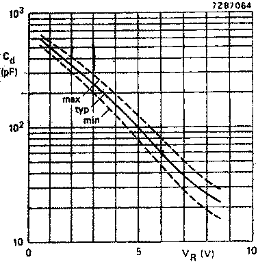 BB112 |
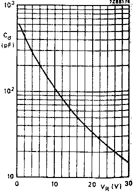 BB130 |
Typical diode capacitance as function of reverse
voltage; f =1MHz. (Philips: Semiconductors Part 1, Sept. 1982)
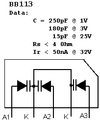
Found some surplus BB113 type diodes, they might also be a good
idea to use as a twin diode out of the three (BB113 data). Please
correct me if I've misunderstood the connections.
11) PE1ABR LF
antenna
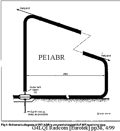
Another broadband antenna suggested for LF/MF-reception is
described by PE1ABR
Quoted from Radcom, Eurotek.
Quadrature AM demodulators, see page C11
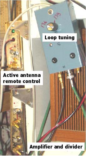
12a)
Accessories in the shack to operate the remote
units
It was little space left in the shack, and I don't wish to remove
the old equipment, so the remote control
units must be put on the side of the shelf. Here is shown remote
control for active aerial (1),
remote control for frame aerial (2), and wideband amplifier
sometimes needed, see info below.
If it is still a desire to ground the centertap, it could be
connected via the loop-ground.
NOTE: The
difference between the remote operated active antenna and the
remote controlled loop antenna is that
1) the supply voltage for the preamplifier for the active antenna
is fed via the coax cable, while
2) the tuning voltage for voltage variable diodes are taken via
the coax cable.
12b)
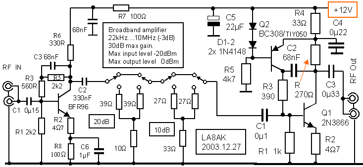
Broadband distribution 30dB amplifier
with BFR96 and 2N3866
It is an old construction, and later modified, see item 13b.
Max gain +30dB, max input level is -20dBm, max output 0dBm,
Attenuator: 10+20dB. Max input without attenuation is -30dBm
-3dB bandwidth 22kHz...10MHz, see photo..
Any Si PNP transistor will work, used TIY050=MPS3702.
12c
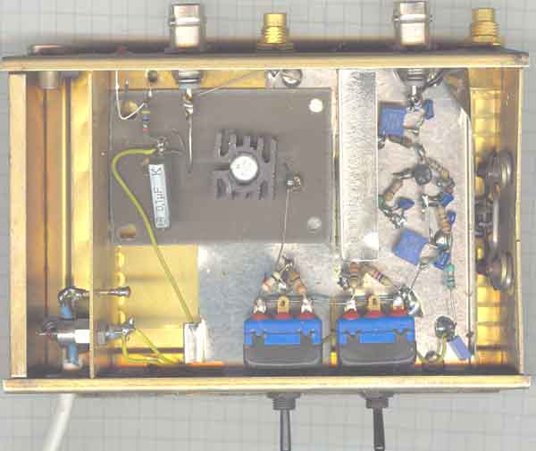
Wideband distribution amplifiers. The first
amplifier using BFR96 and the 2nd using 2N3866.
Between the amplifiers are connected 10 and 20dB attenuators -
mounted on the DPDT switches.
The BNC and conhex connectors on the input are connected together
for greater flexibility, as are
the two connectors on the output. I normally use conhex type
connectors, but sometimes need BNC,
with the two different connectors available no transition is
needed.
The connection of more than one input or output is theoretically
incorrect, and should only be
done when you know that it doesn't impose any problems, if you
need correct match, try using
6dB 2-way resistive dividers, 10dB 3-way dividers, or better....
2- and 6-way transformer connected dividers, see
page m2 item 2.14 and 2.15. They have low
loss,
but the problem with true dividers is that you must terminate
unused ports when not used.
12d)
Another broadband amplifier with good dynamic and low noise, and
suggested values shown for 1-30MHz (12dB gain, NF=4dB).
See the book edited by
William Sabin og Edgar O. Schoenike "Single.sideband systems
& Circuits" from 1987.
It is important to keep the right direction of the winding,
otherwise you build an oscillator. A two hole core is
supposed to give optimum coupling between the two windings, with
1turn and 4 turns.
See more info on /la8ak/12345/n16.htm , a problem with this amplifier is that
returngain is somewhat too high
13a) 136kHz indoor
test-antenna to check resonnance of a frame antenna
To check that the antenna is working on the desired frequency,
you cannot rely on a signal on 138.8kHz
when it is over 25dB attenuation when you listen on 136 and the
antenna is tuned to 138.8kHz. It is usually
no other signal available than your own signal generator.
I use this simple loop connected to a signal generator inside the
shack, and it provides a reasonable strong
signal to listen to on 136kHz band with 0.5-1V RF. Use
Wande&Goltermann PS-3 with a frequency counter
to check the accurate frequency.
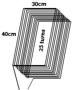
The indoor test-antenna is not critical. It has 25 turns 0.5mm
PVC coated wire on a 30x40cm (12x16in)
frame and it is stowed away somewhere in the shack.
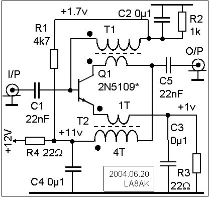
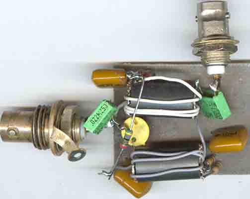
13b) Amplifier for
VLF signal generator
 |
 |
If you don't have a generator capable of 1V RF level, here is
shown a 20dB gain amplifier, maximum output
level is 40mW (+16dBm or 2V RMS in 50W). The limiting factor is collector voltage swing.
It uses off-the-shelf components. Current drain is 120mA, but
depends on the E-B voltage of the PNP transistor
and resistor R4. The transformer has 250µH per coil and it is
useful for a broadband-amplifier. Other suggested
transistors types are Q1=BD135, BD137, BD139, Q2= 2N3906, BC557,
BC558, TIY050.
Bandwidth within -2dB drop of gain is 80-3500kHz, so if you need
something to cover larger range you must
use a UHF-transistor like 2N3866, 2N4427, 2N5109, BFR96 or other.
To increase the gain on lower frequencies, a higher
inductance transformer and larger capcitances are necessary.
0.1µF was chosen simply because it was free, it is
almost too small for 136kHz.
With only an RF choke the gain will decrease a few dB, but the
maximum RF level will inctrease by the same
amount. It is explained in Solid state design for the radio
amateur (pp189 fig 18) that output impedance increases
and as such you loose gain.
The amplifier is mounted on 35x75mm pcb laminate. Cooling fin is
needed and it gets quite hot.
The red capacitor over the transformer is output connection. I
haven't the faintest idea what or where
the ferrite cores comes from, but there were hundreds of them,
and they are free, possibly easy to find
a better type for those who like to pay.
Some more broadband low power amplifiers are shown on page-c14
14) 2. May03. Antenna tuning meter for 136kHz:
For tuning LF antennas, I have for some time been using an
oscilloscope to monitor the current and voltage
waveforms at the TX output. Resonance occurs when V and I are in
phase, and the load resistance is 50ohms
when V/I = 50. This is very easy to use provided a scope is to
hand, but not very useful if it isn't. A VSWR-
bridge can be used, but it only indicates the degree of mismatch,
so tuning is still a matter of trial and error. So
with a mind towards future /P operations, I have built a
self-contained tuning meter.
The prototype has 2 meters - one indicates phase, while the other
can be switched between voltage and current
to determine the load resistance. The circuit is slightly more
complex than a VSWR bridge, but not by very much -
it uses 12 diodes, 3 toroid cores and a few other passive
components. It does not require an external power
supply, and is usable with TX power between about 20W and 1.8kW.
I have written a 3 page article about it - it
is a pdf file of about 190k, so too big for the reflector, but I
can e-mail it as an attachment to those who are interested.
Cheers, Jim Moritz
73 de M0BMU
Jim's PDF file can be
found via my 'Links' page:
http://www.lf.thersgb.net/links.htm
Mike, G3XDV
The
impedance measuring bridge has been moved to page m31
see also
section M for measuring instruments
15)
Field
strength measurements on LF.
From: Dick Rollema [mailto:d.w.rollema@freeler.nl]
Sent: 13. november 2002 10:55
To: rsgb_lf_group@blacksheep.org..
Jan_Martin and All,
You could use your loop aerial, together with a selective level
meter, for field strength measurement
on strong signals by using the coupling loop on its own with the
tuned loop open circuit. The voltage
induced in a loop is given by Terman , first edition, on pg813:
Induced voltage in the loop:
u =
2p . e . N . (A / l) cosq
in which:
e
(epsilon) = field strength, volts per meter
N = number of turns in loop
A = area of loop, square meters
l
(Lambda) = wavelength, meters
q = angle of signal direction
in respect to the side of the loop
cosf = 1
when loop is turned for maximum signal.(<= 0°).
At the low frequency concerned I don't expect that signal pick up
from the electric field by the unscreened loop
will disturb the measurement. To check this you could turn the
loop 180 degrees. This reverses the polarity of
the magnetically induced voltage. If this produces a different
reading then you could take the average of the two readings.
In the tuned loop, when open circuit, no current should flow that
could affect the magnetic field. In practice the loop is
not completely open circuit because of the distributed
capacitance between the turns. But hopefully this effect is not
too disturbing.
You could rig a duplicate loop without the tuned winding to check
this.
I use a square untuned single turn loop of 1 square meter. It is
made of coax with the outer shield open at the point opposite
the take off point. On DCF39 (500km distant) it produces a
voltage of 4.9 microvolt, easily measured by the SPM-12.
The impedance of the loop is so low that it makes no difference
whether the 75 ohm loading resistor at the input of the SPM-12
is switched on or off.
I expect that at your location you will obtain a suitable reading
as well. Do it during daytime, because after dark the
sky wave may wreck the measurement.
Once you know the FS of DCF39 you could use that to calibrate
your other aerials.
73, Dick, PA0SE
JO22GD
15b. Field strength formula:
A description of my Field Strength Meter for 136 kHz can
be found on several web sites.
I just found out that on some web sites the formula for the power
that produces a
certain field strength is wrongly given.
The correct formula is:
P = 0.0111(E *d)2 in which:
P in watt
E in mV/m
D in kilometre
* means multiplication
or since some cannot read this, I repeat it:
The correct formula is:
P = 0.0111(E *d)^2 in which:
P in watt
E in mV/m
D in kilometre
* means multiplication
73, Dick, PA0SE
JO22GD
16) Noise generator for LF
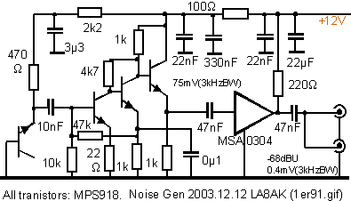
On page c13 is described a noise source
giving 0.5mV into 50ohm, measured with 3.1kHz
bandwidth using Siemens D2006, and it covers down below 50kHz.
Measured broadband
it gives 30mV deflection (-17dBm), but it covers up to far above
30MHz. Since bandwidth is not
a problem for LF the gain could be pushed somewhat more,
particularly if some bandlimit filter is
added. A 10MHz LPF is also shown, but for LF the frequency limit
could be well below 1MHz, see
ARRL's Amateur radio handbook for LPF construction and scale the
filter down to the desired
frequency. L-input filter type is supposed to give least trouble
ON7YD,
Amateur Radio, Longwave ressource page
see page-994 for complete list of technical topics.
17) Calculating coil, capacitors,
inductance:
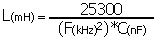
Below 1MHz, use nF, kHz, mH
Above 1MHz, use pF, MHz,
µH
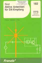
Siegfried W. Best; RPB 182
"Aktive Antennen für DX-Empfang" (ISBN
3-7723-1821-5) - 1982.
Interesting to see some ideas to improve the
antenna element, but we have learnt a lot more about
making transistorized amplifiers since the book was
written.....See W1FB/W7ZOI's Solid state design
for the radio amateur. ....Just my opinion

Last updated 2005.03.03