
Technical
reflections III
Links to other pages:
 C11 technical topics I
C12. Tecnical topics II
C21 QRP notes *** Note that some topics are moved to
this page ***
 |
 |
White Noise generator (I) for HF receiver
selectivity checks
Noise level measured into 75ohm 3.1kHz BW using Siemens D2006
level meter: -80dBU (77.5mV)
from zero to 1MHz and drops 3dB on 17MHz. Decrease the first
coupling capacitor (68nF) to 10nF
to increase the lower limit to 50kHz. The amplifier is copied
from one of LA7MI's constructions,
combined with a general audio amplifier. A noise level was needed
to test vintage receivers and
requirement was not beyond 10MHz, but it seems that some further
bandlimiting circuit could well be
used, particularly since I am not interested in noise spectre
below 200kHz.
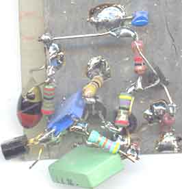
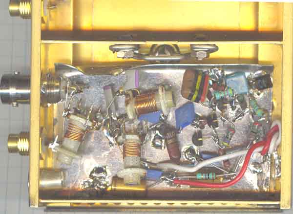
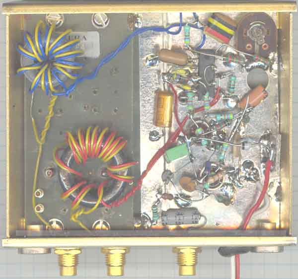
Picture: Zenerdiode connected (E-B junction)
MPS918 at left side and the other devices follow as
on the circuit diagram. The component values were first
calculated, but I used the components which
was closest, but it seems to cause no problem because of the
heavy DC feedback. Reducing first
emitter resistor (from 47 to 22W) to
the half value will increases the output by 3dB on the lowest
frequencies.
 |
 |
White Noise generator with MSA0304 booster
amplifier. The picture shows the 1st
version noise generator which has -68dBU 75 ohm o/p (3.1kHz BW),
while the 2nd
has -66dBU (rel.0.775V).
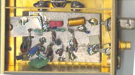
White noise generator II.
The 2nd version built on tinned iron plate, output is measured
using Siemens D2006 selective level
meter to -66dBU 75W (3.1kHz BW), and
30mV into 50W using LA7MI broadband
voltmeter
(described further down this page). Suppose this is quite high
level and I am not sure if it is worth
increasing it further since the main task is to check surplus
receivers. Level on 10MHz has dropped
by 2dB. The noise generators were housed in NERA surplus boxes,
and the 2nd room is not used.
Have kept the conhex connectors since they are free and available
in very large quantities as well as
different cablelengths with connectors. It is some some minor
changes of components for the two different versions. It
increases the gain by 3dB, without any noticable change of
frequency response, but the only measurable difference is that
the version has 3dB, so it seems no problem to copy the circuits,
the only importance is to choose a device with 6v e-b breakdown
voltage. The box measures 100x80x30mm
10MHz BAND-LIMIT Lowpassfilter.
It seems to be an advantage to bandlimit the noise since very
wide band noise has quite high power level and it is no good idea
to load more than necessary, the problem arise in particular when
you want to increase the power gain on the generator output side
further (broadband noise power measures 30mV 50ohm or -17dBm).
So I decided to add a simple 10MHz LPF. A filter is described in
ARRL handbook 1996 and the values scaled. Supposed I had the
fixed coils for 390nH and 1µH, but didn't find them, so I had to
use slug tuned coils.L1=L3=400nH, 8turns on 5mm core, closewound
0.3mm enam. cu wire, dip with 100pF to 25MHz L2= 1000nH, 14turns
closewound on 5mm dia core, 0.3mm enam cu wire, dip with 100pF on
15.9MHz.
3dB cutoff frequency for the LPF is 14.5MHz (measured with white
noise and Siemens D2006 selective level meter).
Concept.
The concept for measuring receiver bandwidth response using the
described units. Have not installed the
program because I wished to build the units first and find some
properties to consider before the project
could be tested. But have tested it with IC706 and discovered
that it was limitations possibly caused by
harmonic distortion in this receiver so it is better to build an
external module which you can adjust and
check that it works properly first.
The data program can be found at http://www.visualizationsoftware.com/gram/programs/setup.exe
Add-on productdetector
Circuit diagram for the add-on demodulator to test RX IF (and RF)
responses. The gain and current
seems somewhat low and could be pushed using the extra resistor,
but it seems to be quite high gain
as it is. 5mmho forward conductance into 4700ohm load is a lot,
but voltage drop over the resistor is
low - only 3V, so it is some room for increase. Functional
circuit diagram for S042 is shown further
down the page.
Power feed for an active probe can easily be modified using two
extra components on the input winding.
 |
 |
The external demodulator under test
(IC2=IC3=CA3140S)
The box measures 100x80x30mm
Previous measurements to see that the demodulator is
working properly:
Using HP4934A as fixed LO (-10dBm/135ohm) and RX (600ohm
bridged), with Wande&Goltermann
PS-3 generator -42dBm(150ohm) the measurements were found for
offset of centerfrequency (50kHz),
and it is almost the same level for frequencies above and below.
Because of some limited signal
frequency available I could only check this range now. It seems
that carrier leakage without carrier
balance control is somewhat high (-40dB) compared to max output
level (+10dB), but it is easy to add,
some 25dB improvement is achieved (see similar arrangement on page L1).
It seems difficult to make a useful construction without an
active LPF, but the output variation must be
considered for later measurements.
Detector output rised by 1dB when LO level was increased by 6dB.
| Generator offset frequency + F (-42dBm/135 W) | Detector output level (600 W / bridged) |
| 0 | 0db (0.775V) |
| 15kHz | -0.5dB |
| 18.5kHz | -1dB |
| 22kHz | -2dB |
| 24kHz | -2.7dB |
| 30kHz | -5.3dB |
Suggested probe (IF pad) based on VLF
active antenna construction. It is fed from the demodulator -
with current through the input winding, 100W
to +12V and 330nF decoupling.
The trim.pot.meter is adjusted for suitable input level (not
overloading the demodulator).
More details about the active antenna (10kHz-40MHz) is shown on page-L2 .
Homemade "RS232C" connector for Garmin
etrex GPS
Telefunken Spez801 receiver moved to page 17s
Mechanical dimensions for HC49 (HC18/U)
type xtal
The alternative is HC50 (HC25/U)
90° hybrid (RF).
Stein, LA7MI mentions that the hybrids used in CDG2000
transceiver (Radcom 2002) could perfectly well be home-made,
he has built a similar hybrid for 10.7MHz for use with xtal
filters. The Mini-Circuits hybrids for larger bandwidth are much
more complicated than this simple circuit.
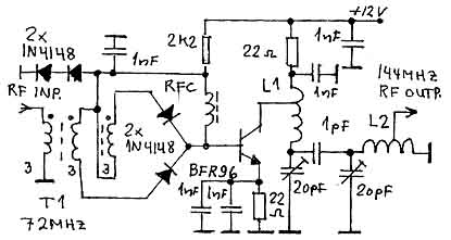
Passive 72/144MHz frequency doubler
with extra amplifier.
Made some experiments with passive and active
push-push-doubler (2-way rectifier-type).
Here is one which I found useful for one project using 72MHz
exciter in a 2m transmitter. 1N4148 was chosed because
DJ8ES mentioned the limit for mixers is around 150MHz, and wanted
to use inexpensive components when it is not
neccessary to throw money out ot the window.The SRA C502 4m
exciter delivers 20mW.
The input transformer is trifilar wound on unknown ferrite core
(3+3+3 turns). An active doubler using 2x BFR90 was
also tested, but the result was worse, so I kept this solution.
Magnetic coupling between the output coils were tested,
but was found to be somewhat too complicated, so I chose the
capacitive coupling for something near critical coupling.
L1=L2 5t 18SWG, 5.5mm ID 15mm long, T1 3x3 turns 0.3mm enamelled
cu wire on a two hole core, RFC1 3t 0.3t enam
Cu on ferrite bead.
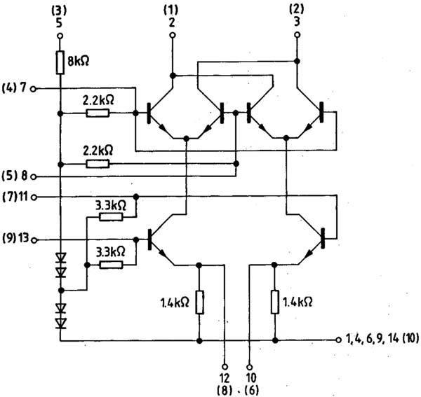
S042E/S042P circuit diagram,
connections in parenthesis apply to SO42E (metal house). SO42P is
dual in line type.
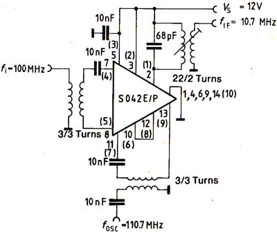
S042E/S042P
test circuit. Numbers without paranthesis applies for
DIL-package, while those in paranthesis applies for the
metal package.
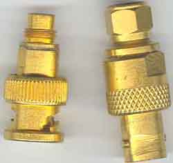
Transition from BNC to conhex and vice-versa (75W)
RF speech processor, see page
b89
CW keyers and paddles, see pg c18
.... I really don't understand where the hum comes from.

Last updated 2004.07.28