
17s. Telefunken
E381S.
Other similar pages:
e11
Receiver's Intermediate Frequency List - 1
e13
Receiver's Intermediate Frequency List - 2
e12
Data for German communication receivers
Telefunken
E381S receiver.
Telefunken E381H/E381S
(receiver type 1V2): RES 094 (RF), 3x RE 084 k (Det. + AF)
E381S. It covers 14.6kHz-20MHz, and seems
to be a receiver used by Luftwaffe and Kriegsmarine.
The early version E381H seems to have been designed when
Luftwaffe was a part of Kriegsmarine. It is mentioned as a simple
Allwellen-empfänger and covers 14.6kHz-20MHz.
The later version has a meter for anode- and heater-voltages, the
mount differs on different models. It is several versions of this
receiver, some is mentioned in DL2IE's book. An older version of
E381S has the meter mounted different. Mine is 39'version and has
pot-cores for some inductors. It has two wavetraps (notchfilters)
100-300 and 300-1000kHz., the switch which was intended for
crystal detector is now used for wavetrap (Note
**). I suspect the emergency crystal detector was for the
Navy, not for Luftwaffe - if they had no supply voltage, they
couldn't fly. The first version appeared in 1932, and the last in
1942. So one should be impressed by the delivering program kept
by Telefunken.
| Bereich | Frequenz |
| 1 | ... 14,6 ......... 45,5 kHz |
| 2 | ... 41,7 ....... 136,4 kHz |
| 3 | ..122,9 ....... 411 kHz |
| 4 | ...366 ...... 1 250 kHz |
| 5 | 1,160 ...... 4,290 MHz |
| 6 | 3,480 ...... 6,100 MHz |
| 7 | 4,800 ...... 8,350 MHz |
| 8 | 6,600 .... 11,000 MHz |
| 9 | 8,950 .... 16,000 MHz |
| 10 | 14,000 ...20,000 MHz |
Documents: The receiver is mentioned with
simplified circuit diagram in Fritz
Trenkle: Die deutschen Funkführungsverfahren bis 1945 pg53,
and it is also possible to request documents from DL6VW, Werner
Gierlach.
Verwendungzweck: Telefunken-Universalempfänger
("Brotkasten") Spez 860 Bs (E381S).
Vier-Röhren-Zweikreis-Geradeausprinzip mit Rückkoplungsaudion.
15kHz ... 20MHz in 10 Bereichen.
Verwendung in ortsfesten oder Schiffs-Funkstationen [für
Detektor-Notempfang eingerichtet. (DL7SK J.
Richter)**]
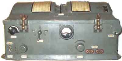 |
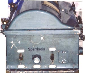
E381S (Model 1939) seen from the front. It differs from
earlier models in that the meter is mounted with a frame.
It has also two sets of rejection circuits instead of only one,
and somewhat different notch ranges
 |
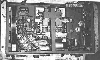 |
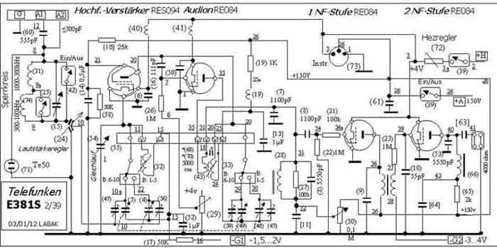
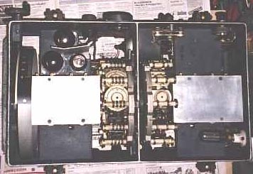
E381S Circuit diagram
A difference from the earlier version is that mine
has no coherer, but an extra set of notchfilter
Power requirements:
+3,8V 0,35A
100V 20mA
-1,5V zero current
-3V zero current
see page e97 for power supply.
Suggested circuit to simplify bias requirement.
Alternative valve type:
Re084K may be difficult to find. Another suggestion is Re074,
which - apart from the filament voltage is exactly the same as
1H4G (2V filament voltage), so you may mount an 1H4 in the socket
for RE074 and adjust the bias voltage to suit the alternative
valve
Last update: 2004.03.09