
Reflecties door LA8AK - part II |
a. Antenna topics
b. Rig MODS
c. Amateur radio experiments
c11. Technical topics I
c13. Technical topics III
c21 QRP notes
n23. Lowcost xtal filter construction
d. VHF/UHF experiments
L. VLF
technik
m. Measuring instruments
g31.
Miscellaneous equipment, BC and audio
g4. Power supplies
g30. Different
radio-related topics
Power supply topics are moved to page g.1 and surplus psu's to g2
Improving SL6440 application
Problem with Plessey SL6440 is low gain, normally -1dB, and gain
optimum
is different from noise optimum (NF=10dB), but when operated with some
extra component on 24V this can be improved according to Stein
Torp, LA7MI.
A 0.5µV signal produced 10-12dB (S+N)/N with SSB filter in a
receiver, so RF
amplifier is still only needed for 28MHz and higher frequencies.
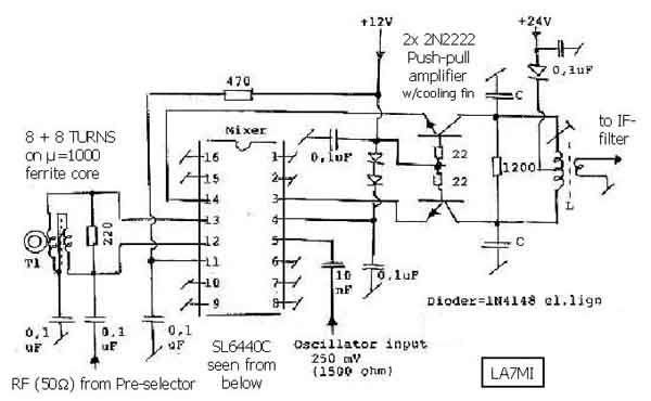
The complete circuit diagram for the improved SL6400 mixer -
based on an article in Amatör Radio nr 10/2003
Terminating mechanical filters.
Got the last item from Stein Torp LA7MI who bought some
surplus 455kHz mechanical filters
25 years ago, but had no data for termination impedances. He
first tried to measure the
transducer inductance and got 900µH.
Trimmed the circuit according to fig.1, but wasn't satisfied with
the passband ripple.
Fig.1 First attempt to use an unknown mechanical
filter (LA7MI July 2003)
The filter is USB type with 3.5kHz BW and -60dB down is 6kHz BW.
After having checked a surplus receiver which had similar type of
filter, he found another termination which performed far better,
with only 1dB
ripple in the passband. The surplus receiver is General Dynamics
R-1051A/URR, made by Elmer in Italy. (2003.07.14)
Fig. 2. The improved termination of the 455kHz
mechanical filter
Lowcost xtal filter notes are moved to page n23
See application for lowcost +35dBm mixer, page n16
my planned AF staircasemodulatorproject
Logarithmic amplifier used as a part of LA4MH's VSWR/PWR-meter.
This is a club project at LA8D with 18 participants
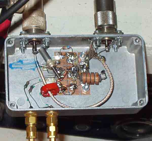
VSWR detector for power meter.
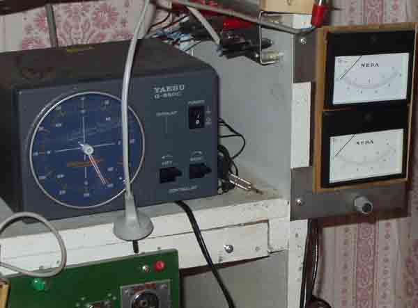
It is important to use two large meters. It is a lot of arguments
for what one needs or not, but too often the requirements are
dictated before experience.
In my experience it is of minor value to know the exact VSWR,
more important for newcomers who have little else to talk
about....
More important is low VSWR, say less than 1.2:1, and after some
years of operation one is less critical - the world is larger and
more interesting than talking about such things, more important
is to see that the transmitter provides the power one should
expect, to avoid that power output is 50 when you thought it was
100, so some timeconstant is a desire.
My planned PC controlled sweep oscillator board to cover
50-100MHz, and lower frequencies with binary dividers
Control circuit for Jotron 2m 250W VHF power fet amplifier
Under editing:
Bias regulator princip circuit
Bipolar transistor biassing principle
Single BDV65A mounting details and suggested pcb pattern
Dual bias regulator for Magnetic TU8131 2m 150W
PEP linear amplifier (BDV65A)
The best bias transistor uses a PNP device as thermal sense diode
and MC1723
voltage regulator, or the simpler two transistor (per power
transitor). It is sometimes
difficult to find suitable power devices which have similar diode
characteristics to the RF
power devices to be biassed, in this case I found a lot of
devices with 0.8V base-emitter
voltage, and they could not work in a circuit where 0.650V is
needed. However BC547
(NPN general purpose transistors) could work, provided they have
sufficient low thermal
resistance to the chassis, some clamps were made to achieve this.
The pass transistor should be high beta BJT, a MOSFET is no good
idea since the gate
voltage may vary a lot, with too much varying emitter current
through the sensing device,
and the regulator may prove to be unstable and the linear
amplifier is no more linear.
see page D21 for more info and D25
Bias regulator for Motorola 70cm 250W power amplifier
G3SEK's RF Power
Amplifier Optimization Boards ++
The Triode Board
The Tetrode Boards
Intermodulation distortion - effect of screen supply
stabilization
G2DAF Amplifier - original articles for reference
European transmitting tubes
On 11 Aug 2003
19:31:58 -0700, mark--aren10@yahoo.com (Mark Aren) wrote:
Hi All,
I just tripped over this rather interesting publication by
Philips.
It covers a ton of basic RF
design and links to examples
etc.
http://my.semiconductors.philips.com/acrobat/other/discretes/philips_rf_manual_3rd_edition.pdf
I am not connected with Philips, this just looks like a neat and
free
RF design guide...
Mark.
On 13 Aug 2003 06:33:01 -0700,
Mark Aren wrote:
I finally printed the whole of the manual out and spotted this
document reference towards the end :
http://www.semiconductors.philips.com/acrobat/other/discretes/philips_rf_manual_3rd_ed_appendix.pdf
Does anyone have any links to similar documents they would like
to
make available (I nearly said 'share', I have been in California
way
too long).
Mark.

2004.11.28