
QTH-locator DS80b, WW/Loc: JO38
Devoted
entirely to Amateur radio
QTH-locator DS80b, WW/Loc: JO38
d2. General CW/SSB technik for 2m
d6. 6m techniques
d7. 70cm techniques
d21 Converting Magnetic
VHF combiner amplifier TU813 (2m) and TU8062 (70cm transmitter)
d24 Converting NEC pager
PB-3102A (Norwegian text)
d25 Converting Magnetic
pagers PBS817 (and info for Compact9000) (Norwegian text)
d27 Evaluating NMT450
equipment for amateur radio purposes
d28 NOKIA NMT450 base
station equipment
d31 Constructing
VHF/UHF/SHF beacons
d32 VHF/UHF power
modules for signal generators
m11. Griddipmeters
m12. VSWR- and wattmeters
...
 |
 |
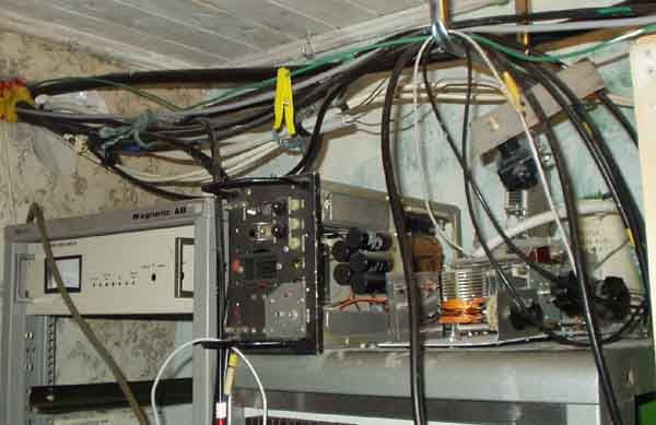
 |
 |
 |
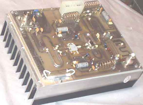
VHF/UHF Power amplifiers for the technically skilled radio
amateurs
 |
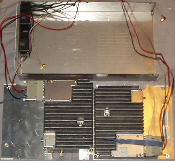 |
1) NEC 144MHz 150W PEP PA available as surplus
about a year ago in Norway, click on the pictures for further
details
2) 2x NOKIA 432MHz 200W PEP power amplifier available as surplus
in Norway.
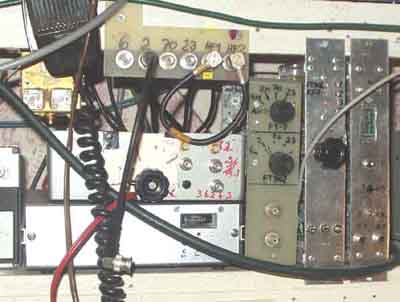
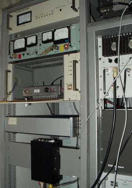
1) Panels for selection of RX-antenna/transverters, transceiver
keying/PTT, together with 136kHz
and 2m transverter
2) Simplified view of shack wiring for VHF/UHF/SHF operation
using transverters and remote operated equipment.
Started off using 23/70cm transverters
mounted above the roof, but it later turned out to be complicated
since I needed to combine more equipment,
so around 1983 another arrangement was made. This has been
optimized many times. The most important seems to have been to
use positive short-circuit-proof
voltage on transmit cable to control the swithing, with
indication if the remote equipment is not ready for operation.
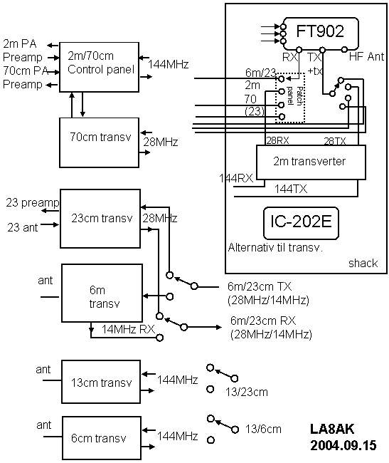
3) General principles of operation
with remote VHF/UHF-transverter, power amplifier and
pre-amplifier
Principles for operation with transverter. Basic diagram for
remote controlled units
for 2m/70cm/23cm rigs. The following
circuit diagrams are based on this system,
but it is possible have some remote indication of failures or
manual blocking.
Remote PA may have a fault, or only cable for RX is connected.
Some decide to
use only single coax cable, but I wish to have the possibility to
listen on one band
when transmitting on another and have no problems finding
sufficient amount of
secondhand cables from work.
The use of +12v (shortcircuit proof) solves the problem with PTT
that a shortcircuit
to ground would otherwise cause the amplifier to switch on, while
in this case it
indicates a state of failure, which is indicated on an LED in the
shack.
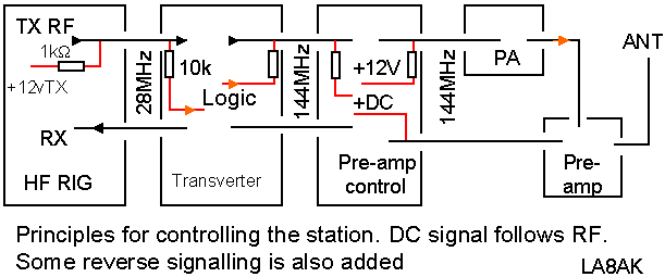
4)
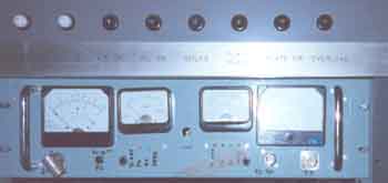
Pre-amplifier and RX/TX-control-box
for 2m and 70cm. Meters are cheap and directional couplers even
cheaper - to make.
So I've included a meter for each pre-amplifier (with remote
C/O-relays) and RF power output reading for each
band. Only small meters are needed for antenna-relay and pre-amp
current. The RF-indications may have delay or
direct reading, it is just a half LM358 to convert to peak
reading on whatever testpoint.
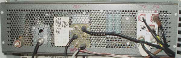
The RX/TX control-box seen from rear
5)
Simple PIN diode switch for 2m linear power
amplifier
Coax cable lengths: 'A' = 'C' = l/4 = 34cm (not very critical
not much power passes here, RG58 is good, but I would prefer PTFE
type which is easy to solder), 'A' is only used as a simplified
RF-choke and any impedance cable will do here.
Coax cable 'B' - any length will do, but here passes the power
Capacitors: Use 2 in parallel, 470pF or 1nF for low impedance
D1 Unitrode UM9401 or similar, D2-D3 not critical RF switching
type, D2 may be a smaller PIN-switch type, use 2x 2 smaller
diodes to limit the dc in each diode.
Resistor value depends on diode types and TX power.
see diode data at http://www.datasheetarchive.com/3359.html
6)
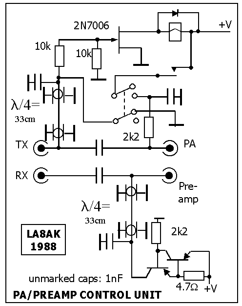
Pre-amplifier control-box. It
is important that it is shortcircuit proof. If any faults occurs
such that the voltage does
not reach the remote pre-amplifier the relay switch to pass the
transmit signal to the antenna, and the pre-amplifier is
protected. The meter is not shown, but is connected over the 4.7W resistor.
Note that the TX-line is DC-shorted when the switch is in OFF
position. The transceiver or transverter senses this and
cannot operate, I use this function when PA is not switched on,
but only want to listen on the band. Since the equipment
is not in my shack, it is also meant as a signal that PA could
have a faulty condition and the transmitter should not be
able to send. Since it is only 1mW from FT-902 or FT-7 into the
transverter it is no problem and need not feed the signal
into the HF transceiver, but LED's on the transverter indicates
that the control box is disabled.
 |
 |
7)
a) My old pre-amp control board. Used then
Kenwood TR-7010 with single coax cable for receive and transmit
and control signal did not follow the RF, but used separate
PTT-line (which is a bad practice because short circuit
will operate the power amplifier). If you use single cable I
suggest you add the modification shown in the first place
to have the DC-switch signals via the coax cable
b) A suggested circuit diagram using relays instead of switching
diodes, but I measured the diode switching
at Scandinavian VHF meeting, or to say in other words, nobody
could measure any loss at all, so it was approved
by SM6CKU and the rest who didn't like diode switching
8.
Almost as described, not bad!
Diode switch for 2m to split signal for transmitter and receiver
used for Trio TR-7010 transceiver (out of use), measured very
well.
It was made in 1982, wouldn't use RG-174 today, but thin
PTFE-cables since they are far easier to solder without any risks
of damage.
9.
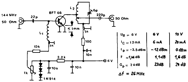
A low-noise pre-amplifier (BFT66) for 144MHz.
Developped by DJ7VY, submitted by DC7CW
DUBUS VHF-UHF Technik 1 pp.153.
This extremely sensitive amplifier is very easy to build, using a
microwave transistor BFT66 (Siemens)
in 50 ohm input impedance configuration. It exhibits an
interception point of -3.5dBm, which is only 8.5dB
lower than that of the VHF receiver with outstanding performance
(using a 3N200 mosfet with NF=3dB)
as it is described in DUBUS 2/75.
With respect to the high power gain (24dB) of the BFT66 an
oscillation-free operation and proper input
impedance is to achieve by excellent grounding of the emitter.
The length of emitter lead shall not exceed
1mm! The other parts of the circuit are not critical. The bias
voltage of the base is temperature stabilized
by three diodes 1N914 connected in series. The collector current
is 12mA at the supply voltage of +6V.
A shield between input and output circuits is recommended. The
coils L1 and L2 are made of 5 turns 6.5mm
dia., length of coil 8.5mm, 1mm dia wire. L2 is tapped at 1.5t
and at 1t from cold end.
A later article in UKW-Berichte by DJ7VY describes some
recommended input filters, and I've also mounted
a quarterwave notch filter for 168MHz, and still the NF was
measured to 1.1dB. The pre-amplifier was mounted
using pcb laminate, with the transistor mounted in a hole at
lower side of the screenwall between input and
output section.
 |
 |
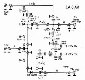
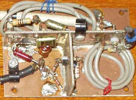
10. Complete 2m pre-amplifier with BFT66.
Note the input protection diodes (BA182 or BA282)
NOTE *) Jumper is only used for voltage supply from the RX-coax
cable. FB= Ferrite bead.
L1 = 3T 14mm dia, 8mm long with 2mm silvered Cu wire (airwound)
L2, L3 = 5T 6.5mm dia, 8.5mm long, 1mm cu wire (18SWG), tapped at
1 and 1.5turns from cold end
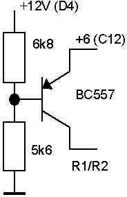
In later version I used a BC557 instead of the
zener diode to stabilize the operational point (see
note at right side).
R1= 4k7-10k, R2 470-680W, R3 =
910-1000ohm, C1= 15pf, C2 = 15pF, C3 27pf, C4 = 12pf trimmercap,
C5=22pF,
C6 = C7=C8 = 470...2200pF feedthrough capacitor, C9 = 12p
trimmer, C10 = 27pF, C11 = 470pF, C12 = 0µ1,
C13 = 450-1000pF chip, C14 = 1nf disc ceramic, D1=D2=D3 = BA282,
D4=1N4002, D5 = 5.1 or 5.6V zener diode.
nominal collector voltage is +6V.
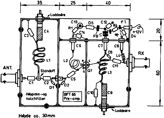
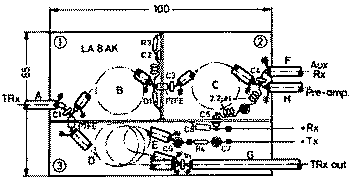
11. Mechanical construction of the
preamplifier. Measures: 80x100 mm.
L1 forms a combined notch and highpassfilter, to attenuate band I
and II signals.
See: 1) article by DJ7VY in UKW Berichte nr 4/77 or VHF
Communication 1/78 for new type of preamplifier
2) AR nr 3/82 and 1/83.
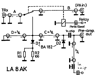
12
Pre-amplifier wiring. The dc wire marked +RX goes to the RELAY.
It is drawings from VHF communications article I
once wrote...
13.
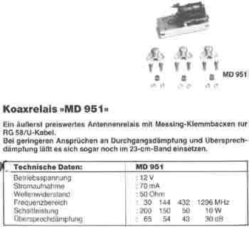
For the mastmounted pre-amplifier I used the MD951 relay with max
200W. You'll find the data for MD951 type
coax-relays in SSB Electronics catalogue 1984. I bought such
relays
at a rally in UK, and have used one for my remote 2m BFT66
pre-amp since 1980. According to Ian, G3SEK
the power limit (not switching power) is 450W on 2m, so it is
really a useful piece to remove before you discard
the rest! Careful to take care of the old mounting hardware as it
is difficult to connect the coax cables without.
14)
Here is my old rig selector
and transverter selector unit
tried to have the receivers through the unit, but crosstalk
between the different RX sides of transverters was a bad
problem, used small screened relays, but result was bad and I had
to revert to the BNC patch panel for receivers/-
antenna/transverters.
I use 14MHz IF for 6m, and 28MHz for 2m, 70cm, 23cm (and 144MHz
for 2320, 5760, 10368 and 24192MHz).
HF drive is from FT-7 or FT-902, and VHF drive is from IC202E.,
separate receivers: Drake 2-B and R-4C, with
FT-7 as spare transceiver.
The drive level from FT-7 and FT-902 are equal, as is the drive
from the 2m transverter and IC-202E, so it is not
much problem if one rig should fail, but I've really never had
such problem for over 30 years. Only had some xtal
oscillator problems with FT-250 (Yaesu), and no problem with any
other equipment for over 40 years.
15)
28MHz transverter remote control boxes used for 6m, 70cm, 23cm
operation. Indication for level, PTT-state and inhibit
16)
Simplified version transverter 28MHz remote control box. TX1 and
TX2 when transverters operates as normally,
while TX2 will not light when the remote part is inhibited
(manually or because of a remote fault).
17)
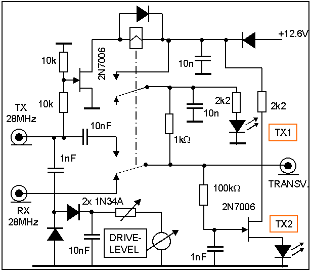
 |
Another version of transverter switching using 2N7006 fets which are readily available here in large amount. An LED indicates that the transmitter is blocked. |
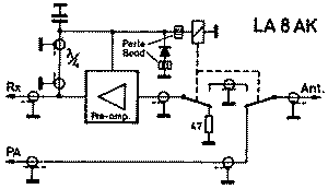
VHF SSB/CW transverter with pre-amp and power amplifier. My
equipment is spread into two different rooms and
some provisions are made such I cannot transmit when the antenna
is not connected or the amplifier is not switched
on. The circuit diagram shows some signalling used for 6m, 2m,
70cm, 23cm band transverters to avoid damaging
the power devices when not all equipment are available
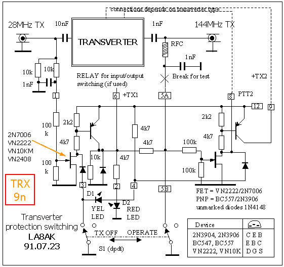
18)
FT-221 modifications. The components marked with
red rings have been changed. The problem with chirp is
the usual problem when you don't understand capacitive pulling
from a keyed stage. And when the buffer is
pulled makes it not better. The key-up attenuation is poor and
has several reasons. Primarily the first stage
has too drive high level, it is then a problem for the next
stage, too, but further improvement can be achieved
by using RF transistors in the IF amplifier stages. BF199=BF224
are readily available in Europe at low price,
so it is really no problem to sacrifice a few (the same problem
in FT-101B). It is also a problem that key-up
voltages for the two stages are not equal, some voltage dividers
must be changed. Then I also replaced the
switching diode on the output with another BA182 which has better
attenuation.
The mod is easy and done in few minutes when you know what to do.
19)
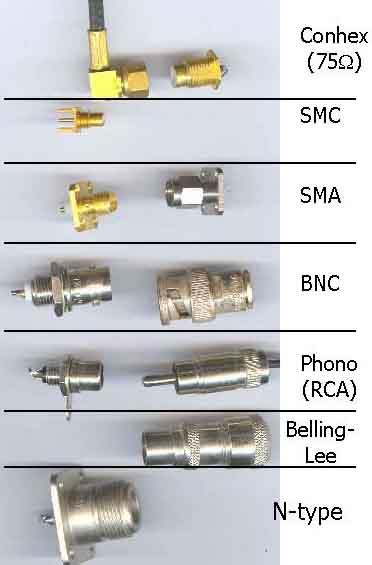
Some commonly found coax connectors.
Conhex type connector is usually found on radiolink equipment and
used for BB and up to 70MHz IF.
Have seen diode mixer for 10Gc/s using conhex type, so I suppose
it has been a 50 ohm version.
I use phono connectors for control lines; keying, PTT etc, but
not for RF. For short interconnections I prefer
conhex or BNC (incl. 136kHz) indoor applications Generally
speaking, I use the connectors fitted on the
cables because often they are mounted proffesionally, and save a
lot of trouble if kept as they are.
Use SO239/PL259 up to 432MHz if they are already used on surplus
equipment. Remember; even BNC
connectors are not good for UHF.
20)
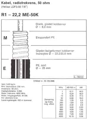
Heliax LDF5-50 7/8" coaxkabel
 |
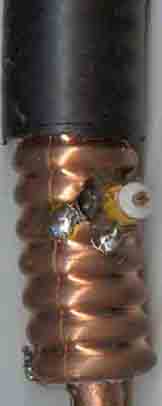 |
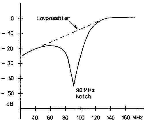
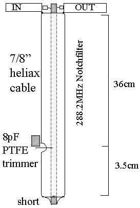
2nd harmonic filter for 2m transmitter, it is
very sharp, and notchdepth is at least 40dB. It is somewhat
tricky to install the trimming capacitor, but it seems to work.
The line is cut somewhat too short for quarterwave resonnance on
288MHz and the length is increased by the capacitor to notch on
the desired frequency.
22)
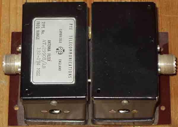
Type No. PYE AT.29908/AB Freq. range 132-174MHz
Antenna filter
A good 2m bandpassfilter found in PYE equipment. Believe I
found them in some PYE R17FM receivers for 160MHz. Have used the
filter on the output of my 2m transverter running 2W RF for some
years without any problems, and the filter seems to be stable.
Have not done any measurements on it.
23)
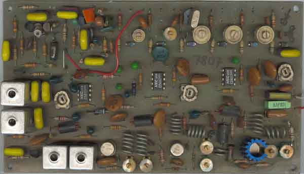
BSP MD510 2m CW/FM 0.8W exciter. Built 3 in 1978
with my own components, but too bad oscillator noise, modified
two for LA3VHF and LA3UHF, and later discarded all, used modified
SRA C400 for 70cm (LA3UHF, LA3UHG, LA4UHF, LA6UHF, LA9UHF), and
PYE Westminster exciter for LA3VHF and LA6VHF (PYE T30FM) with
DJ2LR 12MHz low-noise xtal oscillators for all 2m and 70cm
beacons.
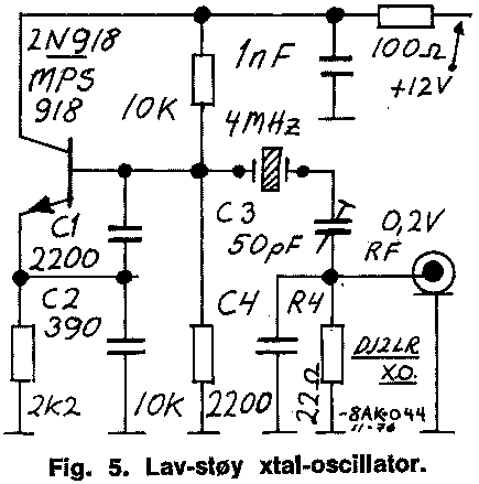
DJ2LR very low noise xtal osc modification shown for 4MHz xtal,
for 12MHz the capacitor C4 should be reduced to 1000pF (film or
NP0)
24)
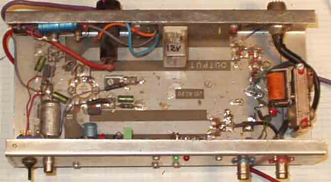
25-30W QRP PA for mobile operation with IC202, a kit made in
Switzerland.
It is still possible to have more cables here.
Seen from above:
2m power monitor and circulator.
2m/70cm control panel
second 2m power amplifier (25W)
70m 50W power amplifier
27)
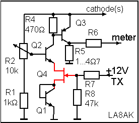
Improved cathode bias regulator.
Q1, Q2 BC237B (2N3904), Q3 BD140 or other suitable PNP power
(MJE2955), Q4 2N7006 or any other,
R5, R6 chosen for suitable values dependent on meter current
range.
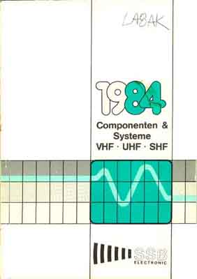
Still a useful book for finding VHF/UHF circuit diagrams and
components (SSB Electronics 1984, Componenten & Systeme)

2005.04.07