
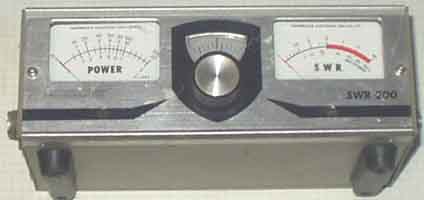
m12. RF power- and VSWR-meters
m1.
LC and Q-meters
m2. RF
detectors, level meters, attenuators, dummy loads, signal
dividers
m3. RF
signal- and power generators
m11 Grid
dip meters
m13
Accessories for measurements
m21
Norwegian instruments
m22.
Old measuring instruments
m23.
Signal-to-noise-meter
#12.1)
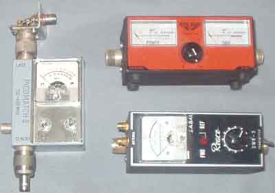
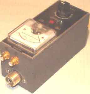
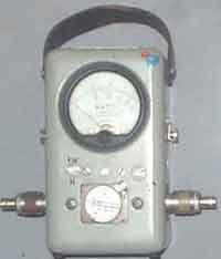
Some cheaper "SWR" meters. The Norwegian Picomatch
II to the left is quite good instrument for 144MHz,
believe it is specified quite strict, but some day the instrument
people don't like any old instruments.......
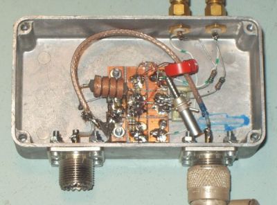
The Inter-Power SWR-5 - upper right - "isn't worth a
penny". Got it from a mate to use with a beacon, but I burnt
it out with only 3.5-4W morse signal on 70cm. Removed the bridge
and installed my own pick-up line (suggested by LA8OJ) and now it
is fb for VHF/UHF. The old Hansen, Reace or whatever
make "SWR-meter from 1968 (from J. B. Lowe) or later has a
relatively good bridge, it works fb on 2m - provided careful
operation, sensitivity is very good on 2m! It is easy to destroy,
but works fb with level down to 10mW, have used it on 180-190MHz
to test TV-receiver antennas using Wavetek Model 3001 signal
generator, but mounted N-connectors to make it look sufficient
professional at work, see next note.
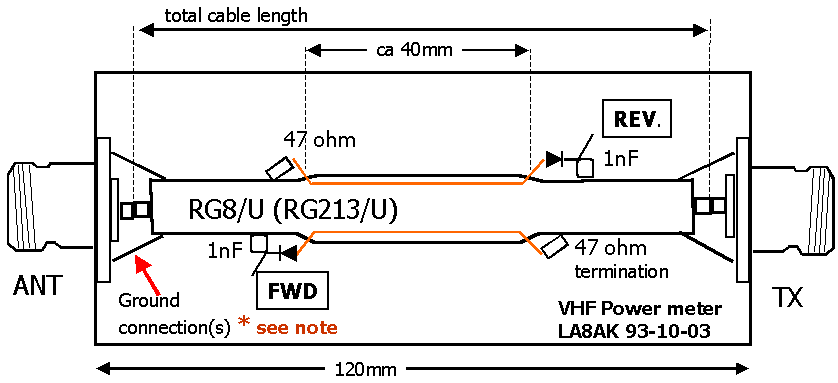
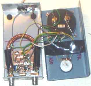
The Inter-Power SWR5
was renovated and since the meter and box was so nice looking I
decided to keep it and remove the useless bridge. Mounting wire
is pulled under the braid for a length of 40mm. It is easier for
the old type RG8/U, where the braid often is somewhat looser than
for RG213/U. I wouldn't think about using RG214/U! It was some
struggle to mount the bridge, and solder in the right order since
it is just as must space as you need.
NOTE* Ground connections from braid to coax connectors should be
the last mechanical step to do.
#12.2)
Another application of the same technique. It is so easy to build
pick-up bridges, it is just fun.
Here is my 2m line - permanently inserted between the PA to
antenna.
Suppose RG8/U type coax-cable is better than RG213/U since the
braid may be somewhat loose,
but must not be dark and corroded.
#12.3)
The old single-small-instrument SWR-meters
are not much good when using an antenna
tuner (see first picture), but addition of two external meters is
a vaste improvement, so i fitted
two phono connectors on the old small SWR-meter, to 2 external
meters with potmeter on an
aluminium plate, and hide the old instrument somewhere in the
back of the shelf.
Just add two coax-connectors and hide the old coupler somewhere
in the background and
you don't need to see it any more. My main HF operation has been
with 100W output on
80 and 40m cw and the coupler (SWR-meter) is good enough for use
with an antenna tuner.
#12.4)
My own directional coupler
for HF - made as an alternative to the old VSWR-meter mentioned
above. It is sort of amateur 'design', you know when it is not
possible to make to equal units, forgot which handbook I found
it, but it works good enough for my desires, and when you are an
electronics engineer with laborating background you know what is
important or not, this is good enough for me! It was wired in an
afternoon and I don't want to waste more time on a simple project
- at least unless I didn't find a reliable construction.
#12.5)
Oskerblock. May
select between 50 and 75 ohm line. Probably not the most accurate
instrument to have in the shack, but I never really bothered.
With some years of experience one understand that it is not
important whether the power is 80 or 100W, and I could always use
the Bird model 43, but really, it is just not important. Accuracy
is for those who don't know, and not important for electronic
engineers like me - in
my own home!
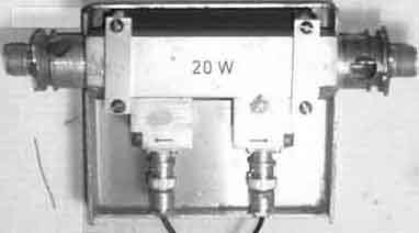
#12.6)
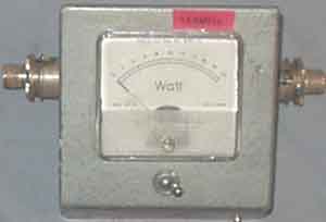
VHF power-/VSWR-meter
Another 2m power meter I built. Wished to see what sensitivity
could be achieved with an extra LM358 op-amp, so the sensistivity
for FSD is only 80mW. When you know that the connectors are
BNC-type, you'll understand that the coupling loop is quite
small. The probes consist of insulated pvc wire under the braid,
terminated with a germanium diode in one end and 50W in the opposite end.
#12.7)
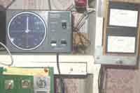
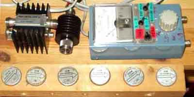
More power ranges with
Bird Model 43.
Model 43 RF wattmeter is too expensive to buy for
experimenters. Got mine in 78 - in the darkest socialist ages -
when it was good tactic to overprice items provided they paid
sufficient taxes, and VAT was higher and the social democratic
government very pleased. Got a 1W 150MHz surplus probe - very
useful to measure 2m exciter power levels. Per, OZ1CFO
found a 2GHz probe at an army surplus shop (Midtjydsk
reservedelslager, Viborg).
Have heard of other types, too, so you may find odd types
elements which is not described in any available documents.
Morgan, SM6ESG discovered a trick where you just
pulled the probe and found a stable position where the
sensitivity was reduced 6dB.
A trick is to remove the plastic cover on the probe by pressing
the sides and lurking very carefully with a screwdriver to push
the cover away. There are some screws under the type label, but
you won't get anywhere into the element by removing the label
(according to Henrik, LA4MH)
It is quite easy to find the patent description for Bird
Model 43 on http://ep.espacenet.com/
and write "Directional wattmeter" as search word.
You'll have two hits, then choose "US2852741",
then there is a page where you click on the patent - coloured ink
in middle of the page, choose 1/16, 2/16 to read the different
pages
.
A way to store the wattmeter probes on the side of a shelf
It would be insteresting to see if the circuit is patented and if
it was possible to find it, we found the Bird Model 43 documents
quite easily.
click on <http://ep.espacenet.com/>
and write (copy) into searchword "Directional
wattmeter". You get two hits, then clikk on
"US2852741" for Bird Model 43, then it is a page where
you click on the patent - coloured ink in middle of the page,
choose 1/16, 2/16 to read the different pages
#12.8)
R&S VHF surplus RF power meter (VSWR-meter)
A Rohde&Schwartz instrument of the higher
price class, but unknown model. It has been used for broadcast
transponders where high quality is demanded, but prices doesn't
matter. Got for free since the fool at the surplus shop laughed
at me and thought that nobody needed an instrument for 88MHz.
Have only tested it for 2m, the only problem is to calibrate i,
but calibration is usually not important.. Would believe it is
likely the probes may be adjusted for proper operation on UHF as
well as VHF.
Inside view of the R/S VHF power meter. The
coupler probes may be adjusted for almot any degree you may
desire.
Suppose it is not such thing as power limit for this coupler. It
was easy to convert the dezifix connectors to 83'type (SO239).
Found similar probes in some other equipment.
#12.9)
R&S surplus UHF power meter
NAD.
Rohde & Schwartz NAD
(470-2800MHz) with couplers for 10W and 1000W.
Had it calibrated 10 years ago. Only problem is dezi-fix
connectors, but fortunately got transitions for the larger type.
#12.10)
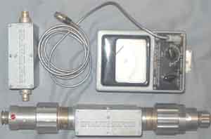
VSWR coupler from discarded 900MHz mobile
telephone base station
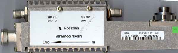
LME coupler for NMT900 system
 |
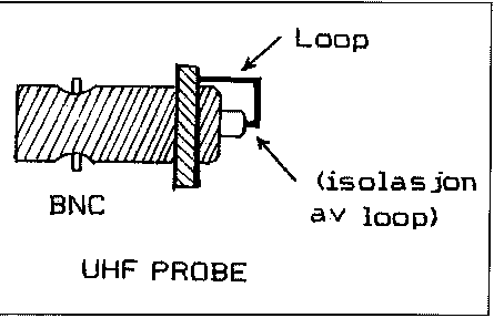 |
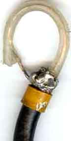
#12.11. It is important to have
available an RF pick-up tool as shown for RF level meters and
frequency counters, it will work over the frequency range
10-500MHz, and may also be used to inject signal from a generator
to RF coils when the receiver seem death.
Above 1000MHz with strip-line this is not effective, the coupler
should be plane as shown in the second figure, but it is
important to remember insulation for the pick-up wire.
Some German coax connectors of the
50...60's.
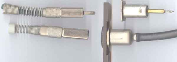
Above is the coax connector usually found on CF instruments from
Wandel&Goltermann and Siemens, and below is the Fernsehen
connector which is practical for video switch panels. I use them
for selecting between HF antennas. (Also shown on
page m1)
 e/m
e/m
2004.10.07