
30a) Transmitters, Lo40K39a/d
> modulators <click
here>
Links
to other pages:
30b 2nd
part Lo40K39 tx (Modulators)
30e
S10K/L transmitters
30m
80W.S.a transmitter
k91
Correspondence concerning radio communication at Batt. Vara
Betr.: Funkverkehr zw. den Batt. "Hanstholm II" und
"Vara".
Lorenz Lo6K39, Lo6L39 receivers, see 24L.
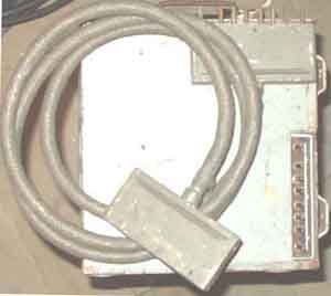
Power cable for Lo40K39
 |
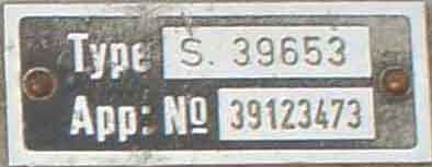 |
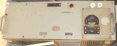
S 39653 (Lo40K39). Type plate.
 |
 |
 |
 |
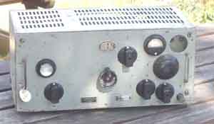
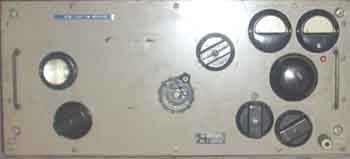
Lo40K39/S 39653 seen
from different angles
3x RL12P35
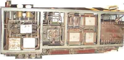
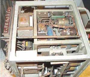
Lorenz Lo40K39a and d:
 |
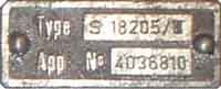 |
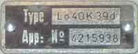
Type plates for Lo40K39d (S23725/I
) and S18205/III (Lo40K39a)
S18205/III
(Lo40K39a) front plate and
scale removed
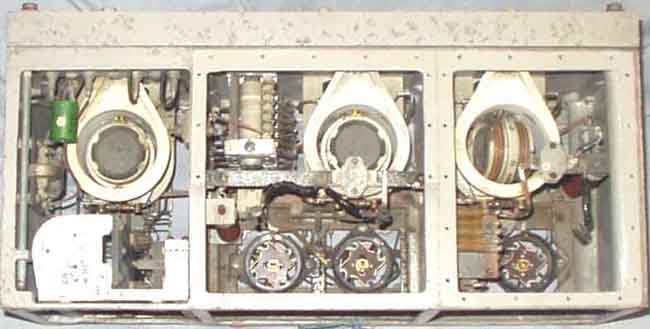
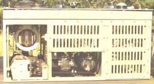
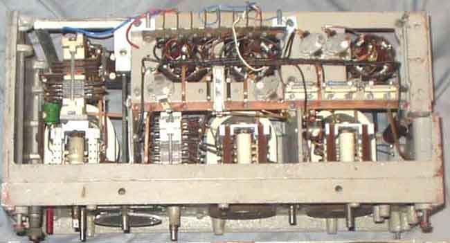
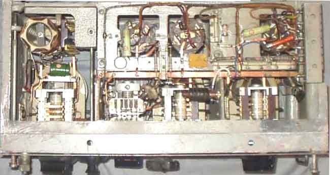
S18205/III (Lo40K39a) seen from above
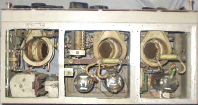
Lo40K39d (S23725/I) seen
from above
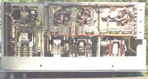
S18205/III (Lo40K39a) rear view, note
the "different" switch to the left and the extra
capacitor below.
Lo40K39d rear view. Note the coil and the larger switch to
the left
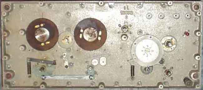
S18205/III (Lo40K39a) seen from below. Note the power connector below/behind the valve
sockets.
The chassises seem to be equal and it is an empty space for power
connector on the lower left side.
Lo40K39d seen from below. Note the power
connector to the right
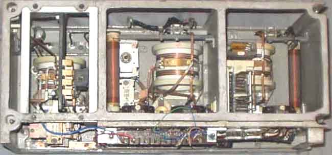
The two models are quite different, the antenne coupler is
different, the power connector (flat contacts) may be
supposed to plug into a socket when the unit is installed in a
box.. The S18205/III (Lo40K39a) is a wreck, almost
all drives are stuck, and a large job must be done, but - as
always the worst part is to find a way to dismantle the parts
without breaking anything. It seems that Lo40K39d is operational,
as it was when I swapped it for a TS500 in 1976.
While the reason for LA3WU for giving me the other set was that
it was some problems concerned.
Lo40K39a (S18205/III) 5,0-16,6MHz -
without match coil for 8m antenna
Lo40K39d (S23725/I ) 3,0-16,6MHz
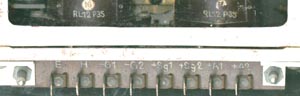
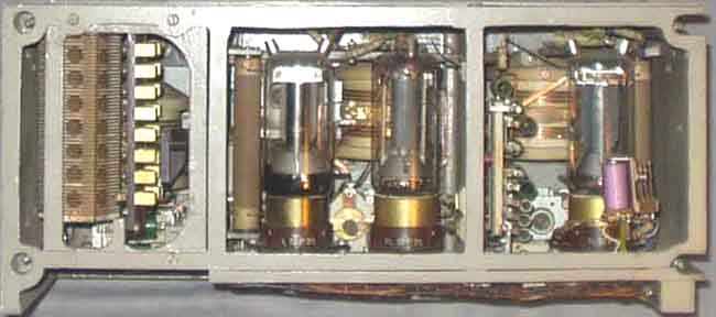
Lo40K39a has power connector with flat contacts behind the 2x
RL12P35.
See
also LA6NCA's notes for Lo40K39d (you can identify his set from
the antenna tuner switch and coil)
 |
 |
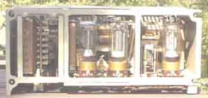
Power supply for Lo40K39 with built-in
modulator (RV12P2000), this is a quite unusual version.
The unit belongs to LA6NCA
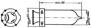
RG12D60 Rectifier valve for SGLE0,2/2R Netzanschlußgerät
Reference:
Die deutschen Funknachrichtenanlagen bis 1945, Band 2 [Fritz
Trenkle] pp.196 and 219.
More info for 40 Watt Kleinsender Lorenz and many other
at Seefunk+Seeschiffahrt
(Seefunk Fotos/TX Seefunk Sender)
It was usually a
problem that Lo40K39 wouldn't give pure T9 tone, so often
S10L(FuG10 series)
transmitter was operated on lower voltages and used as a VFO for
Lo40K39 (for amateur radio)
Lo40K39d Technical data
VFO: RL12P35, PA: 2x RL12P35
Power supply requirement
H = 12,6VAC 2A
A1 = +600V 40mA
A2 = +800V 150mA
Sg1 = +150V 20mA
SG2 = +200V 48mA
G1 = -260V
G2 = -245V
AC Mains current max 2.1A
Power output with SGLE0.17/2 = 40W telegrafi overcurrent in
antenna-circuit
Power output with SGLE0.2/2 = 70W telegrafi overcurrent in
antenna-circuit
Frequency 18-100m (3000-16667kHz)
Bereich I : 9200-16667kHz - range I
Bereich II : 5000-9300kHz - range II
Bereich III: 3000-5200kHz - range III
Antenna: Single wire antenna, 8-12m length
Component list:
Pos type electrical value
VFO/Driver
1 valve RL12P35
2 variometer (note..)
3 capacitor 71cm 3kV
3a capacitor 100cm (110pF?)
3b decoupling cap 180cm (200pF?)
4 anode choke 140 turns 0.4mm cu ss
5 coupling cap 5000cm
6 capacitor 5000cm
7 grid block cap 250cm
8 capacitor 5000cm
9 capacitor 5000cm
10 Bereich schalter 3x3 pos
11 resistor 20 ohm
12 resistor 20k
13 grid choke L=0.30mH, R=0,41 ohm
14 capacitor 1000cm (1000pF 2400V)
Amplifier
15, 16 valves RL12P35
17 tuningcapacitor C=62cm, 3kVA
18 decoupling cap. C=170cm 3kVA
19 capacitor 500cm 0,5kVA
20 variometer as pos 2
21 switch 1x6 pos
22 anode choke as pos 4
23 neutralizing capacitor
24 capacitor C=5000cm
25 capacitor C=5000cm
26 Resistor 20 ohm
27 Resistor 20 ohm
28 anode coupl cap.C=5000cm
29 resistor 100 ohm
30 capacitor C=5000cm
31 range switch 3x 3 pos
32 anode current mtr 0-200mA
33 grid block cap C=2cm
33a decoupl cap 7cm (2x vorhanden)
Antenna tuner
34 capacitor C=70 cm 3kVA
35 capacitor C=40cm, 3kVA
36 ant range sw 5x 6 pos
37 antenne current meter 1000 ohm resistance, 0-10 positions,
measuring range 0-3A,
37c RF measure circuit 3A @18-100m wavelength (for pos 37)
38 antenna series coil 7 taps
believe 1cm =1,1pF
details written as mentioned, but some values seems to be wrong,
also some explanations
are silly (not important for the post-war army!). pos 2 has a
note I don't understand
(Translated from Norwegian 2000.04.19 LA8AK)
|
Lo40K39a. Schaltbild
des Senders nach St 510563
Lo40K39d. Schaltbild
des Senders nach St 513503, Ausg. 5
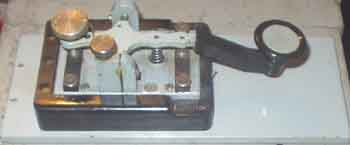
The Junker key
 (e/m)
(e/m)
 b/k
b/k
2005.01.08