
B.23. FT-7 Mods
Links to actual pages:
B)
mods main page
F)
Surplus radio equipment
M)
Measuring instruments and tools
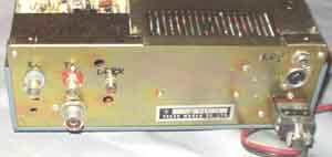
Yaesu FT7. Modification on
the rear shows connectors for proper key-jack, RX and TX BNC
connectors for transverter,
and RCA phono jack for audio output.
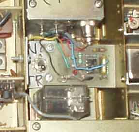
FT 7. Behind
the VFO is some free room, it is used for
(1) a switch to disable the power amplifier when transverter is
used (0.005-5mW RF out on transverter connector)
(2) SSB/CW agc derived squelch board
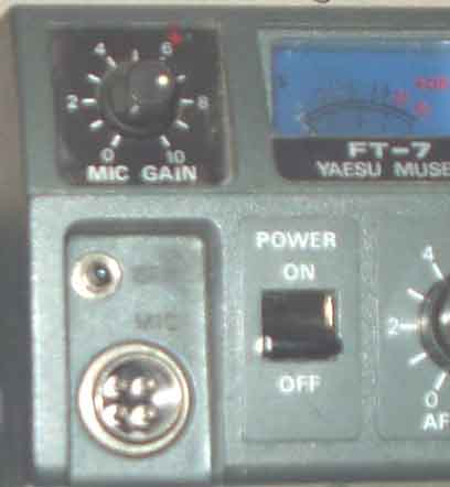
FT-7
Some of the
modifications done for this rig (1982-1985):
1. CW transmit
modification
2a. variable drive level using negative bias oscillator
2b. variable drive level, copying how it is done in FT-7B
3. 10M coverage: 28.0-29.0MHz
4. SSB squelch
5. Transverter facility, separate connections for RX and TX
-"- this also makes antenna connection for external RX
(Drake R-4C or 2-B).
6. Normal key jack installed on the rear with KEY/PTT-connections
7. Changed CW xtal so that I can use USB for CW reception
Unfortunately
no documents are available since somebody borrowed my book 3
years ago
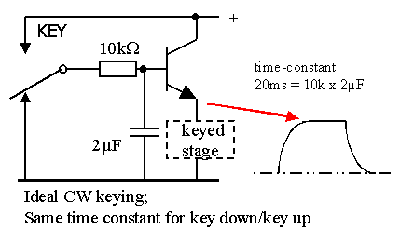
Active CW key-filter
The ideal key filter is shown here. But application of this is
only possible when you build the
transmitter yourself, normally you cannot decide to have the so
easy task......
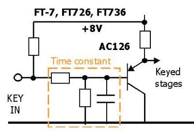
FT-7 key-filter.
Unfortunately the documents are not available and I am unable to
provide the
cmponent values. It is important that the two stages have same
threshold voltages or as
close as possible and this is found experimentally. The voltage
swing is just somewhat more
than needed for perfect on and off state. In some cases the IF
amplifier transistors should be
changed for better RF types with better keying (FT-221/FT-225).
The problem with FT-7 and
FT-726 is that a germanium device is needed in the key-filter. It
may be difficult to find
a type with sufficient high current gain, hfe=50 or more, so
LA9DL used a silicon device in
his FT-726. This is difficult to tell whether it will work or
not, particularly since I don't
have the rig and will prefer never have it in my house.
When writing FT-7, I receive several letters requesting info for
FT-7B. They are completely different
styles and very little is directly similar. I haven't the
faintest idea of FT-7B, only know that LA7XK
had one and I modified the FT-7B noiseblanker according to notes
from LA7XK, Yaesu managed
to make a useful NB in FT-7B, while not in FT-7 and several later
rigs, so one may still wonder
if they really understood when they succeeded or not.........
Clean CW signal from
FT7.
Wrote an article and it is published in SM-QTC nr 3/1983.
The circuit diagram is shown below.
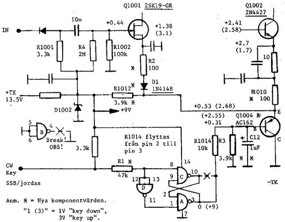
It is important that Q1004 is a high gain germanium PNP
transistor like AC126 or it is not possible to get low enough
saturation voltage over this device. LA9DL used a silicon
transistor in his modification for FT-727, but it requires some
changes, and I am not sure if it is possible here, since all
voltages will be somewhat higher
Skandinaviske artikler å sjekke opp
Articles I've written for Danish/Swedish magazines (sorry, cannot
provide copies from foreign magazines now!):
FT-7 Rent CW-signal (max 1000 lpm)
...........LA8AK QTC 83-03-086 (Improve cw keying, also works for
FT726)
FT-7 Utvid 10m, transverter tilkopling .......LA8AK QTC 85-09-325
(adding 28.5-29MHz segment, transverter mod)
FT-7 TX-gain .................................LA8AK QTC 87-01-010
(TX gain control)
FT-7 SSB-squelch .............................LA8AK QTC 85-07-282
FT-7 Forbedring af-(10m/xtalcal/transv etc).. LA8AK OZ 83-02-.6.
Mods published in Norwegian "Amatör
Radio":
FT-7 SSB squelch for
mottaker................... LA8AK AR 83-12-339
FT-7 Omkopling av xtal-kalibrator............... LA8AK AR
84-02-040
FT-7 Feil i tidlig utgave....................... LA8AK AR
83-02-041
FT-7 Regulering av uteffekten, TX-gain ..........LA8AK AR
83-10-275
FT-7 Xtal kalibrator kan gi intermodulasjon..... LA8AK AR
89-04-105
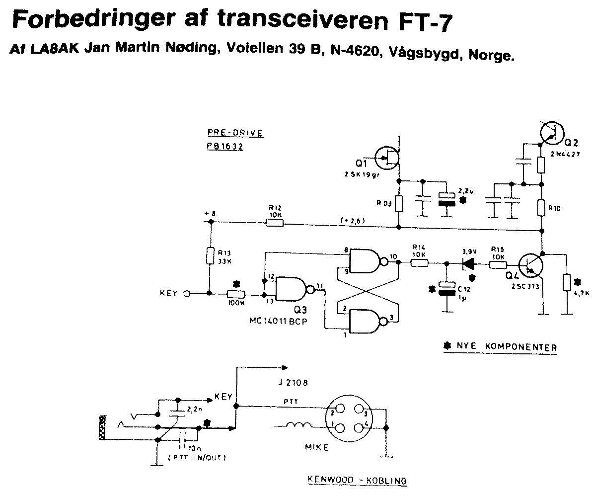
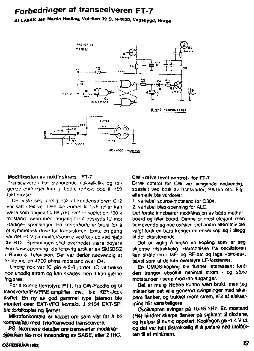
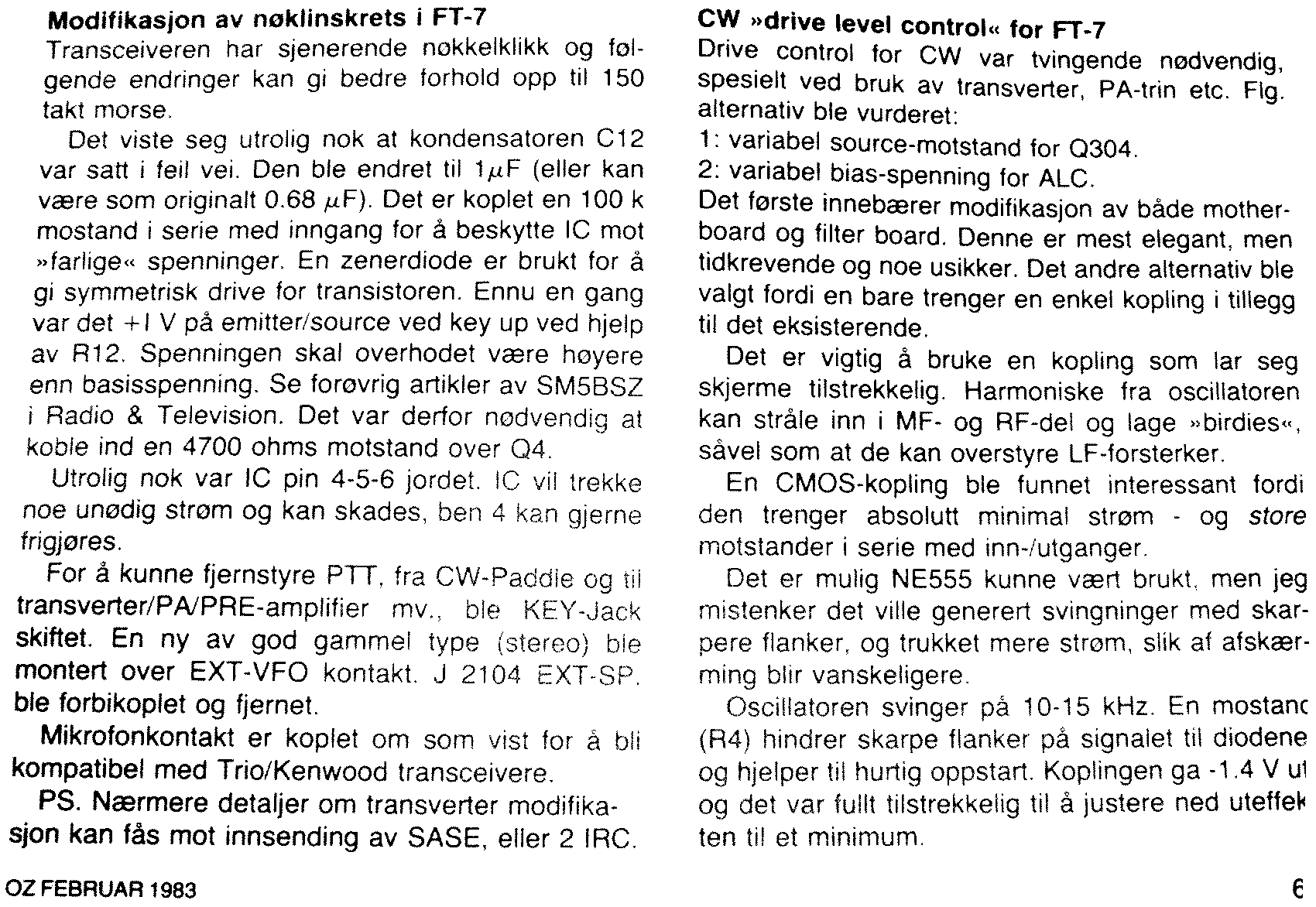
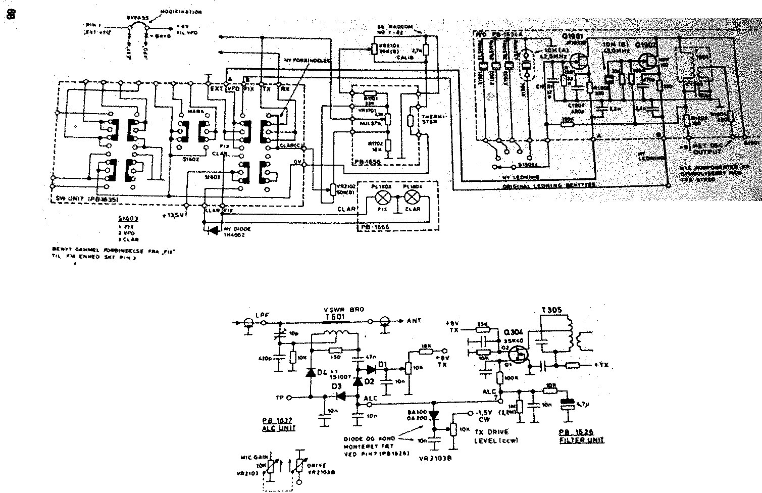
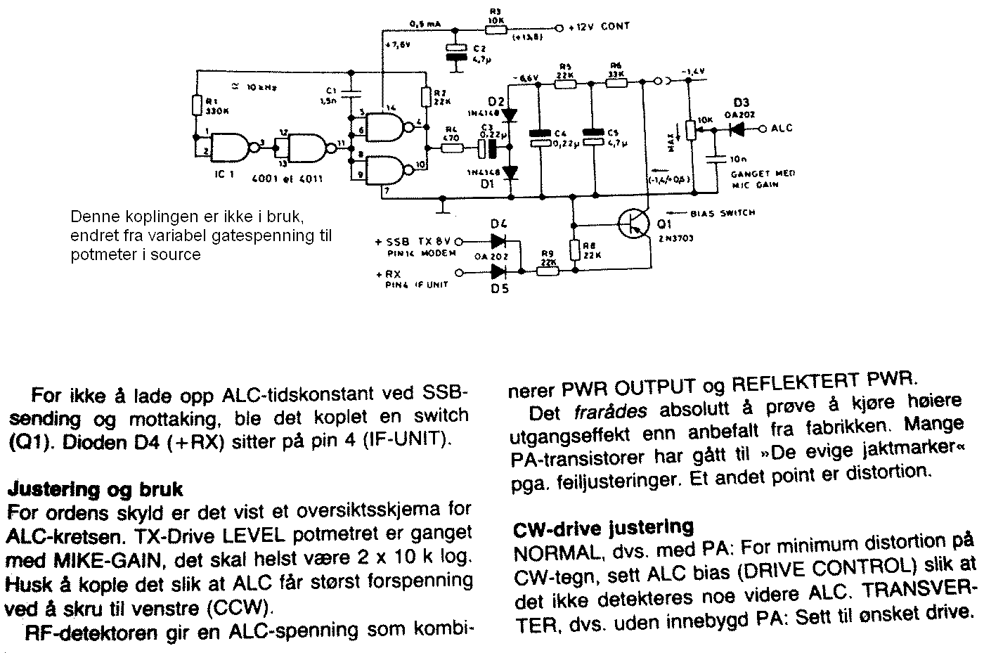
Partly edited copy of the article from OZ febr. 83 (tnx to OZ1HDA
for the photocopies):

2005.01.12