e43 (43a) Signal detectors in ex-German receivers
Other pages:
e12 Data
for German communication receivers
e86
Thermionic Valves (tubes)
e. List
of German radio communication
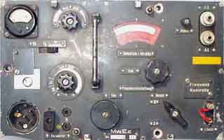 Mw.E.c |
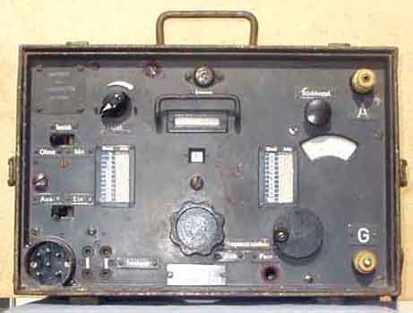 Torn.E.b |
Detectors and audio amplifiers in ex-German communication receivers
The well known series of ex-German receivers
use a standard pentode (RV12P2000).
The number of valves is seldom over 11 in order to keep the
number of valves as low as possible, but still perform well.
Some receivers have another vari-mu pentode (RV12P2001) for [the] AGC controlled stages, but usually it was compromised by using only a RV12P2000. The 2V filament version of standard pentode is the RV2P800, and the 2.4V version is the RV2,4P700 – the AGC version is the RV2,4P701.
Wehrmacht equipment for 2V supply often have an audion detector. It seems this is desirable to pull weak signals out of the noise when diode detectors have insufficient drive level to operate satisfactorily - a similar effect can be achieved using quasi-synchronous AM-detectors using an IC (TDA1576, TBA120, MC1351, NE604 etc). The grid-bias for the audion-valve must be adjusted somewhere between f- and f+ for optimum reception, but it seems that different receivers have different settings, some have variable settings, while most have fixed resistors. So there may be different parameters to bear in mind.
Torn.E.b. regenerative detector. LA7MI, Stein Torp wanted to investigate practices which might have been forgotten in constructing good regenerative detectors for a wide frequency range. He started his 'industry espionage' to test some components in Torn.E.b:
RF choke (59) in anode circuit of detector of
the Wehrmacht version of the receiver (seems to be a resistor in
the version exported to Sweden) has a resistance of 480 ohm. It
is an RF choke wound with thin resistance wire with a pot-core.
He found it difficult to measure the inductance, but managed
later to define the value as 170mH. Self resonance is 150kHz, it
has a capacatative
effect on the higher frequencies. As he wasn't tempted to
desolder the very thin wire from the RF choke, he used the
following procedure to measure the inductance. He removed the
detector valve, and set the sets of coils to a neutral position.
The reaction control was set to minimum. Capacitance seemed to be
27pF, but if he used 170mH @150 kHz the value was 6.6pF.
Audio filter. He also measured the
inductance of the LF-choke in the anode circuit of the detector
stage. He first removed the 500pF capacitor. With
"Tonsieb" set to "mit" you may measure
between pot.7 and 27. It measured 85Henry.
MwEc BFO
A complex series resonnance type. Note the link which goes to the
cathode circuit of the 2nd IF amplifier
 |
Mw.E.c detector
Pentode applied as duo-diode-triode, not widely known, but some
reports exists (G3VA technical topics, Radcom), and on an
occasion 6AM6/EF91 was used by accident as 6AT6/6AV6/EBC90/EBC91
and functioned properly, the "fault" was only
discovered several years later. In the next circuit (T8PL39) only
one diode function is used, while in E52 one diode is used as
detector and the second is used in AGC-delay circuit.
Note that AF gain control is bypassed for A1A reception. This is
not practical for amateur radio (and may easily be changed), but
it must be considered that the German operator needed easy as
possible operation which suited his often limited experiences
with radio equipment. You'll find similar mode switch in E52 and
Kw:E.a. For SSB reception it is impossible not having the
possibility to decrease the RF gain (to avoid overloading the
detector) at the same time as you increase AF gain (since the
level from the detector has been reduced far below normal).
T8PL39 Detector
See the note above (Mw.E.c) for this type of application as
duo-diode-triode with RV12P2000
T9K39 BFO
Similar circuit to the one shown for
Mw.E.c, but one position as free-running oscillator for opposite
sideband selection.
Note that the xtal control is used as calibrator function, too.
E52 Detectors
See the notes for Mw.E.c for application of
RV12P2000 as duo-diode-triode. Here the 'anode' is used in to delay the AGC such that
a certain amount of detected voltage must be present before it is
some variation in voltage to AGC-Line. For Kw.E.a the
AGC-detector diodes are biassed with +4V, but it is not possible
here as the cathode is grounded. In Lorenz 6P203 the cathode
(EBC91/6AV6) has +5,5v level and gives a similar delay.
Note that AF gain control is bypassed for A1A reception.
This is not practical for amateur radio (and may easily be
changed), but it must be considered that the German operator
needed easy as possible operation which suited his often limited
experiences with radio equipment. You'll find similar mode switch
in Mw.E.c and Kw:E.a. For SSB reception it is impossible not
having the possibility to decrease the RF gain (to avoid
overloading the detector) at the same time as you increase AF
gain (since the level from the detector has been reduced far
below normal).
Kw.E.a (detectors).
Detector circuits and modifications are shown on page 22b
 |
My T9K39 was somewhat
amateur'ized, so the connections for anode and screen-grid were
reversed In the audio output stage, it may be a good idea to
repeat the socket connections for those valves once more.
 e/m
e/m
BACK (E)