A1.
Antenna & Tuner topics (ATU)
A. Antenna topics
D.
VHF/UHF/SHF experiments
L2.
VLF/MF loop and active antennas
a2
VHF/UHF antennas
A.71. VHF antennas for CW/SSB operation
A.72. LA8WF's 2m mobilantenne (Wisi)
A.79
VHF/UHF FM antenna
 |
 |
28MHz direction finding antenna (DJ1XK in CQ-DL 12/78). Made a
copy, tuning was not critical,
so it was used to detect some noise source on frequency as low as
18MHz
Read an article by G3LDO about DX'ing from the car using halfwave
verticals and
wished to test the principle with end-fed sloper
for 30m band from home, but it is
some space limitation - a lot of VHF/UHF/UHF aerials occupies the
tower.
According to the calculated results with endfed.exe this antenna
has a louzy efficiency,
but it worked very well for me. I am not a keen DX'er, only like
to have a CW QSO
once in a while, but it was a nice experience to beat some of the
local dx'er from a
QTH which is only rock and very bad ground.
30m ATU for endfed halfwave sloper
has 10 turns coil, 55mm dia. 48mm long (Airdux),
tapped at 1 and 8 turns. Capacitor is 50pF high voltage
(Johnson). The measures are not critical,
the only importance is to get resonnance and keep the turns-ratio
between antenna- and TX-terminals
almost like shown. (The drawing shows a 40m version, but the
corrections given should be followed).
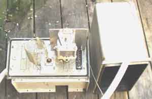
30m ATU for endfed halfwave sloper. ATU was
taken indoor for inspection after several years
in the garden (the lid is to the left). The box is from some old
Philips FTR carrier frequency equipment,
discarded 25 years ago. The white corrugated plastic tube is used
to keep the feeder-line away from soil,
grass and metal parts under the tuner. Be sure to close the far
end such that water does not follow down.
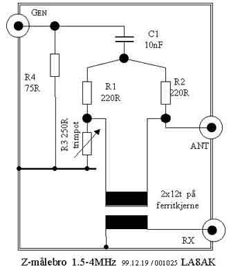
Simple impedance measure bridge
It has the advantage over some other simple bridges that the
actual impedance can be measured with a
voltmeter afterwords, so the impedance needs not be calibrated.
However, using such bridge tells you
only half the truth. Most likely there is some reactive part in
the impedance. Usually you are only interested
in a parallel configuration, meaning resistor in parallel with a
capacitance or inductance. So you just connect
a variable capacitor over the antenna connector - to find the
inductive part, or over the potmeter to equalize
for the capacitance and as such find the capacitance on the
opposite side. The transformer may consist of
2x12turns on a ferrite toroid, the coupling capacitor is supposed
to be .01, but they depends on which
frequency you intend to use the bridge. I've only used the bridge
with signal generator.
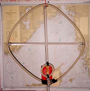
80m magnetic loop for reception. The aerial
was used when static noise from power
line was rather bad. Later the open power-line was modernized to
use cable and the problems
dissappeared. The main loop is 2 turns, almost 60x60cm square.
Used only 1mm dia enamelled
copper wire. RG58 or RG59 might have been better. To
weather-protect the wire it is used a 3
m long corrugated electrical plastic tube. The coupling loop is 2
turns with 10cm diameter.
The capacitors are kept in a plastic food box, it may not be
suitable in the length, so a better
box should be used if it is placed outside in the aerial tower
for months.
 |
 |
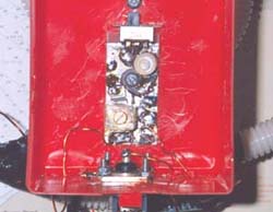
Mounting of the components. It is a switch to choose between
different CW and SSB
segment of the band. It is tuned to 3700kHz with 150pF, and
switches between CW and
SSB segment by adding a 40pF for the lowest segment. The facility
was really not needed
since attenuation with only one setting over the 3.5-3.8MHz band
is no real problem. As it is
shown, it covers 3520-3520kHz within the -5dB points, but was not
more than 15dB
weaker on 3800kHz when tuned for the cw band - without using the
switch facility.
See the remote tuned frame antennas for 136kHz and MW on page L2,
it would be easier to remotely tune an 80m antenna, but I am not
aware if it is worth trying.
Prinzip des Dopplerpeilers
Erfahrungsberichte ueber Entwicklung und Einsatz von
Dopplerpeilern,
DJ3YB, DL9SU, DL4SAK (pp49+) VHF-UHF 1984, München (DARC
Distrikt Bayern Süd)
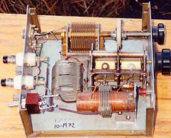
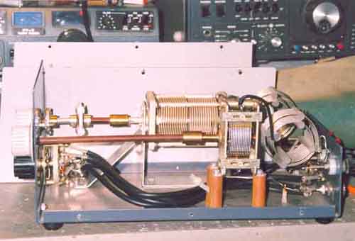
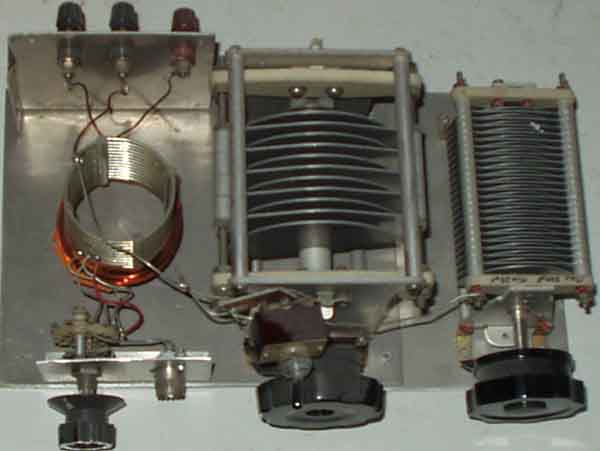
My old Z-match, built in 1972 (type: W1CJL)
Used with FT-dx-500 on all bands, but had some problems on
40m with bad antennas.
Later got KW. E-Zee match which were supposed to be better, but
didn't have more
distance between the plates in the tuning capacitor and
flash-over wasn't better.
Basic circuit diagram for W1CJL type Z-match (QST May 55) - from
the time when the actual
ATU was only a smaller part of the construction, while the dummy
load and VSWR-indicator
caused most headache to homebrew...
C1 = 2x 250pF (used 2x 400pF), C2 = 340pF (used 250pf)
L1 = 3.4µH, 7 3/4t 1.6mm cu (18SWG) 2 1/16" dia, 1
1/4" long
L2 = 1.7µH, 5.5t, 1.6mm cu (18SWG), 2 1/16" dia, 1
5/8" long
L3 = 2.35µH, 6.5t, 1.6mm cu, 2 5/8" dia, 5/8" long
L4 = 1.8µH, 4 3/4T, 1.6mm cu, 2 5/8" dia, 1/2" long
Used Air-Dux coils in some extent, and I am not so sure that the
values were very close to
the optimum, but it worked well. Only problem is flash-over on
the tuning capacitor when it is high
VSWR on 40m, but the same problem applies for KW E-Zee Match.
Either tuner seems to be
somewhat complicated to tune for minimum reflection on the
VSWR-meter.
[Info from: Amatör Radio nr 11/62 pp147-148]
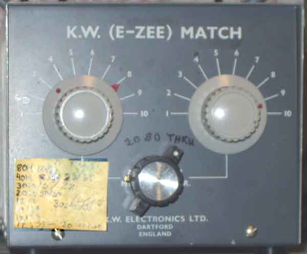
The first important thing to to with KW-EZEE ATU is to mount a
swith on the front and two
SO239 connectors on the rear so you don't need to pull it down
from the shelf when you will
change band from 80 to 20m 30m band works in either 80 and 20m
positions, but 20m
position seems to be somewhat better in my situation.
The modification for simpler operation of the Z-match is shown in
red colored line.
I've mainly used the ATU for G8KW trap dipole, and 20 years later
with LA1IC
multi-band trap dipole (10-80m)
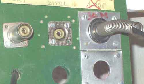
KW E-Zee type "Z-match" modifications
 |
 |
(a) Use of Fernsehen connectors to choose between the different
HF aerials.
(b) Home made transition to BNC.
See C99 for Norwegian texted notes about
connectors and transitions
Alternative antenna tuner for 80/40m experimental antennas
ATU for mobile operation. Simple construction, easy to use when
you only have one
antenna and use it on a limited frequency range. The "fixed
capacitor" consists of wires twisted together.
 |
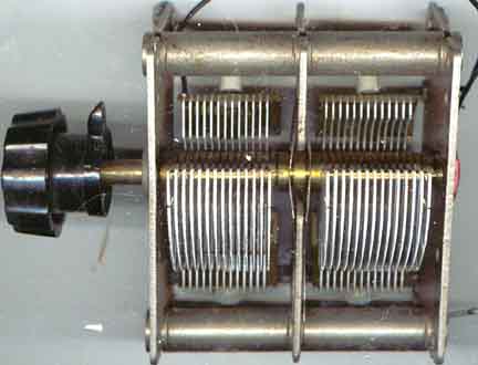 |
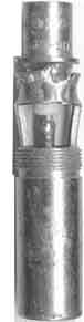
How to convert old type BC-type tuning capacitor to be used in an
antenna tuner. The BC-capacitor was 405 + 455pF, and it is
converted to 2x 30pF or so - high voltage. Remove the marked
plates. Did it 30 years ago, so I cannot remember all details,
but used it with a large AIRDUX coil in a 80m tuner for FT-250
and FT-500. The right picture shows the unmodified BC-capacitor.

BACK
Last updated
2005.01.17