
61) Boatanchors I
pg52 French WWII equipment used by the Germans
pg53a. Dutch (Philips/NSF) WWII equipment
pg62. Some non-military surplus (Boatanchor II)
pg63 British WWII equipment
91n New info

61)
Boatanchors I
pg52
French WWII equipment used by the Germans
pg53a. Dutch (Philips/NSF) WWII equipment
pg62.
Some non-military surplus (Boatanchor II)
pg63
British WWII equipment
91n New info
 |
 |
 |
 |
Some of the
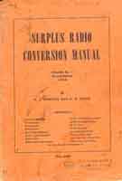
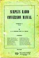
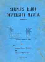
surplus conversion manuals:
Vol No.1 2nd Edition
[1948] R.C. Evenson and O.R. Beach, Techno-Graphic Publications
Vol No.2 [1948] R.C. Evenson and O.R. Beach, Techno-Graphic
Publications
Surplus Radio Conversion Manual, Volume III, William I. Orr,
W6SAI, Editors and Engineers [1960]
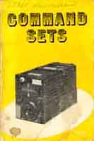
Command Sets as compiled by the Editors of CQ (W2NSD,
W7NVY/K2VOO, W8BAJ/K2OLK. Cowan Publishing Corp [1957]
I've got them as a gift from LA3LC, Klaus, and will not part with
any of them, please don't not ask!
 |
 |
 |
Some other useful books:
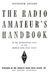
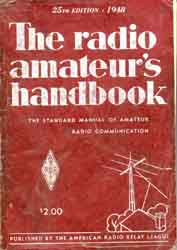
ARRL handbook 1939 and 1948, G3VA: Amateur radio techniques,
Sixth edition [1978] Radio Society of Great Britain
 |
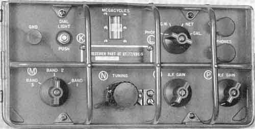 |
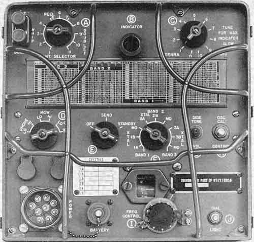
AN/GRC-9. RT77.
Pictures, copied from the handbook TM11-263.
Modifications planned, suppose it would be interesting to test
conversion with product detector
A typical American tradition, compared to German equipment -
little thoughts about power consumption
RT-77(GRC-9) IF: 456kHz 2*1L4(DF91) 3*1R5(DK91) 1S5(DAF91)
3Q4(DL92)
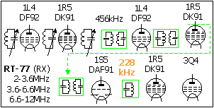
RT-77 (AN/GRC-9) Ranges
2.0-3.6, 3.6-6.6, 6.6-12MHz. RX: IF=456kHz, BFO 228kHz
Dynamotor DY-88/GRC-9-GY. Generator GN-58-A-GY
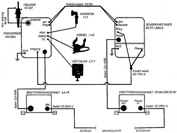
How to install the different units (AN/GRC-9F)
RT-77 Mains power supply
(RA-88/GRC-9): See far below
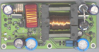
e97. See notes about
LA6NCA's inverter for battery type receivers operated on +12V
supply
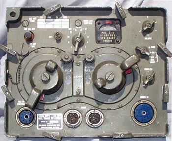
RT67 (AN/GRC-5 ?)
RT67/RT68 IF: 4.45-5.45kHz, 1.4MHz
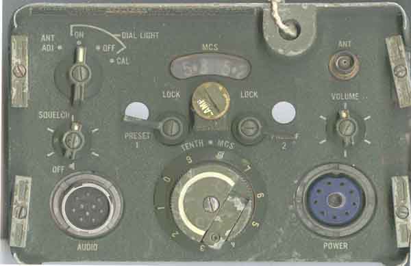
RT-70/GRC. Unfortunately it is only the front, because the
surplus dealer in Oslo would charge a
tremendous high price if I wanted a complete unit, so I
slaughtered it and they were pleased to have
$0.0001 for the scrap metal, instead of $100.- for the unit. It
has been social democracy here, and
we are told that the reason for making surplus unavailable is
because of the bloody Marshall Aid.
 |
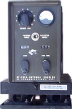 |
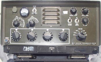
AN/GRC165
with antenna tuner (RF302A)
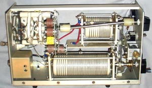
Antenna tuner (RF302A) inside view
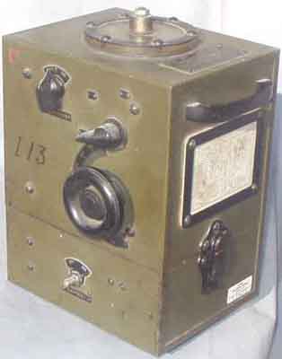
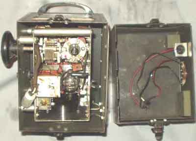
The BC-655 is a
WW-II era low-power transmitter designed to act
as a "target" for radio direction finding sets. It
transmitted
a signal between 17 and 158 MC. You put it out in the field and
used its signals to calibrate your direction finder receiver's
indicators. Was used with SCR-555, SCR-575 and RC-93 sets.
Manual is TM 11-4050.
 |
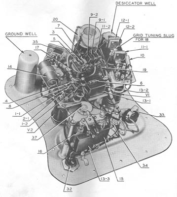 |
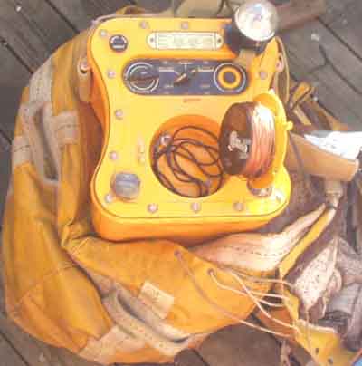
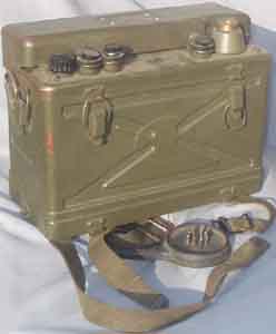
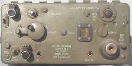
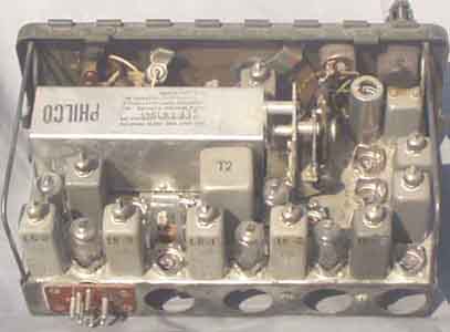
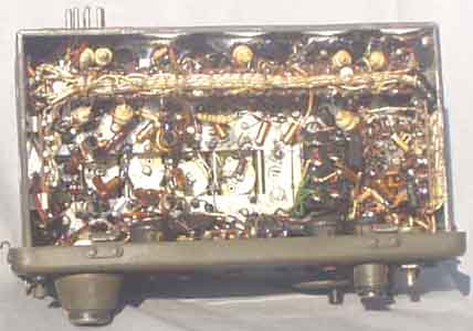
BC778D
(SCR578B) "Gibson Girl" 500kHz emergency transmitter
Tubes: 12A6 RF Osc, 12SC7 1000Hz tone osc.
See also http://home.hccnet.nl/l.meulstee/gibsongirl/gibsongirl.html
 |
 |
 |
 |
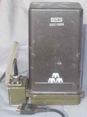
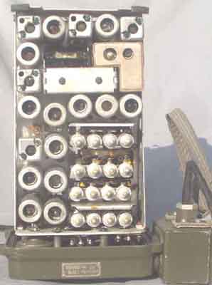
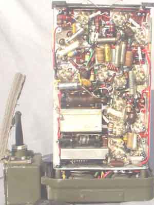
Swedish Army Ra100 VHF transceiver (WS31, BC1000)
...really wasn't aware that the Swedish army is equipped with
NATO equipment, too!
Coverage: 40-48MHz, IF: 4.3 and 2.515MHz, RF= 300mW
 |
 |
 |
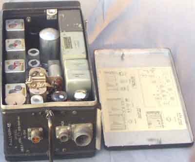
Swedish Army Ra130B VHF transceiver (WS-88). Another
rig from the Allies,
probably not indispensible as another mate once was refused
week-end leave
from the army since the radio communication with this set was
found
useless. (Suppose it
should be among the British sets, and I will remove it from this
page later)
 |
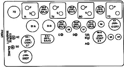 |
R-443/ARN-5D
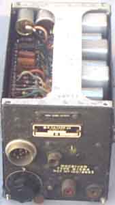 R-3A/ARR-2X |
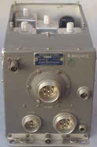 R-15 (28V) R-509/ARC |
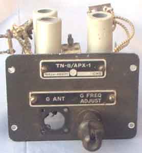 TN8/APX1 |
The AN/ARR-2 is the combined version of the
ARR-1 (also called the ZB-3)
and the BC-946 command set. Used for homing, mainly US Navy.
Highly secret, they weren't declassified until 1949.
The ARR-1 was a small TRF set covering 234-258mhz, using acorn
tubes,
the output was 800-1000khz. This set then connected to the BC-946
which took the signal and demodulated it to recover a morse
signal.
The ARR-1 was also used with ARB and RU-18 receivers, there were
2 studs
on the top of these so it could piggy back, and be powered from
the ARB
accessories connector. Also powered from the power adaptor on the
BC-946.
The ARR-2 was a combination of these, in a Command set sized box,
which tuned fixed channels, and used minature valves in the font
end.
An aircraft carrier had a rotating aerial, which sent out a
different
morse character depending on the direction. When you received
that character,
the aircraft knew which direction to turn to locate the carrier.
To prevent the enemy using this system to loacte the carrier,
several
ideas were used. The range was small, only a hundred miles at
50,00 feet.
The codes were changed daily, so the pilot neede a new code sheet
every mission.
The frequency was high, the enemy had few receivers capable of
tuning
this frequency. The transmitter was only on when aircraft were
returning.
The signal was double modulated, so if you had a single
conversion receiver,
the output signal would be 1mhz, with modulation on that.
Difficult for
an audio stage to amplify, and to hear. The dial was
engraved with the wrong frequency, the 234-258mhz read 34-58mhz.
Although
I have seen one with the correct markings, must have been post
war.
73s
Ray VK2ILV
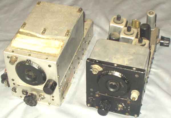
BC453 Command
receivers (probably modified after a Shortwave Mag. article)
IF: 85kHz (SCR-274) 28VDC 1.1A DYN 3*VT131 VT132
VT133 VT134
Suppose BC453 covers 150-560kHz, the BC454 covers
1.5 to 4.5MHz, and the BC455 4.5-9.0 MHz
(although it is vaguely expressed in the surplus manual)
For further info, please check: http://www.carc.org.uk/html/body_fav_rx_2.html
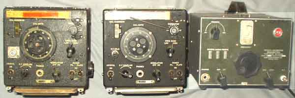
LM21
CRR74028
(Bendix Radio)
LM21 74029A (Mare Island Naval Shipyard)
RCA TE149 Wavemeter
 |
 |
TS170/ARN-5 (Argus Inc.)
BC221-O (Allen D. Cardwell Mfg.)
 |
 |
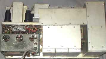 |
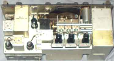
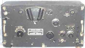
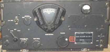
BC312M - a heavy beast compared to
BC348. (Frequency coverage 1500...18000kc/s)
Was promissed a BC342, but received a converted BC312M.
BC-312M IF: 470kHz 12V DC Dyn. 4*VT-86(6k7)
2*VT-65(6C5) VT-66 VT-87 VT-88
BC-342M IF: 470kHz 110VAC 4*VT-86(6k7) 2*VT-65(6C5) VT-66 VT-87
VT-88 VT-97
See SSB conversion notes on page 17r
 |
 |
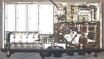 |
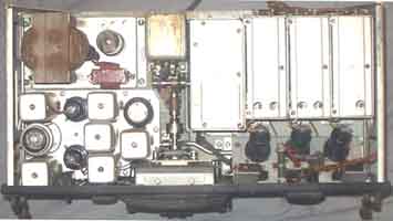
BC348P (Frequency coverage
200-500, and 1500...18000kc/s)
It is supposed that the inclusion of an ex-German mA-meter as
S-meter reduced the value at the auction, but I am pleased.
BC-348E, M, P IF: 915kHz 28VDC Dyn VT65(6C5)
VT48(41) VT70 VT86(6K7) VT91(6J7) VT70(6F7) 6B8
BC-348J, N, Q IF:915kHz 4*6SK7/VT117 6SA7/VT150 6SJ7/VT116
6SR7/VT233 6K6GT/VT152
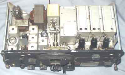
BC348R (Belmont
Radio Corp?) seen from above
From: "John Reynolds" <john@jorey.fsnet.co.uk>:
BC-348-H/ K// L/ R. Belmont Radio Corp.
6K7 (3). 6J7. 6C5. 6K6. 6B8. 6F7. + Voltage Regulator 991.
BC-348-J/ N/ Q. Wells Gardener &Co.
6SK7 (4). 6K6. 6SR7. 6SJ7. 6SA7.
BC-348-E/ P/ M/ S/ O. RCA. Manufacturing Co. Inc.
Tube line up. same as H/K/L/R, in the 41 output stage
 |
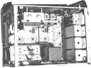 |
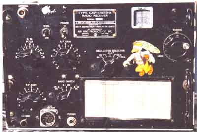
TCS Receiver (CKP46159)
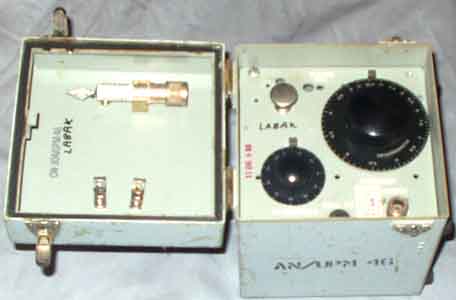
AN/UPM46 microwave spark generator
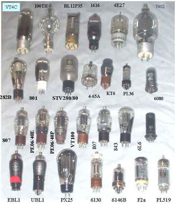
Valves:
VT4C, 100TH, RL12P35, 1616, 4E27, 7402
282B, 801, STV280/80, KT61, 4-65A, PL36, 6080,
807, PE06/40E, PE06/40P, VT100, 807 (Tungsram), 843, 6L6,
EBL1, UBL1, PX25, 6130, 6146B, F2a, PL519
>R-15 (R-13B R-15(28V) R509/ARC) seems to be a
command Set, but could it
compare to BC451-series? he lid is marked R-13B, and the box is
stamped
R-509/ARC. It is without 28V dynamotor - of course!
Sounds like you have post war A.R.C. type 12 series radios.
This is not to
be confused with AN/ARC-12. This equipment is simliar in
shape to the WW2
SCR-274/ARC-5 sets but is completly different.
There is a list of components here:
http://pages.cthome.net/fwc/ARCO.HTM
There is some more info here:
http://hereford.ampr.org/manuals/arcug/arcug.html
T. B
==missed picture==
I have an ARN-6 operational with ID91B/ARN-6. Basically, it's a
selsyn
indicator, 4-wire (3 AC + common) 26V 400 Hz device. In the ARN-6
it's
driven by the selsyn master in the AS313*/ARN-6 loop antenna. The
ARN-6 is a
DC-only device; the 400 Hz AC is generated by a vibrator supply
which also
provides B+ for the thyratrons driving the loop motor.
I've probably told you more than you needed to know, but if you
want
drawings I can scan them from my manual and send them to you.
John Mackesy VK3XAO
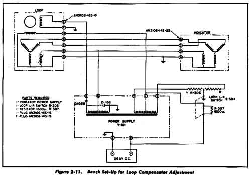
ID91B/ARN-6 circuit diagram
A comparable German application of selsyn system is shown on page 34a
The ARR-7 is basically a RADAR search receiver
and the 6V6 output valve has a dual function as a cathode
follower for the video indicator
as well as operator headphone output.
> the bfo injection is near non existant, is this norm ?
>
The ARR-7 is based on the SX-28 and the BFO circuit looks
identical.
Perhaps you can compare the output with a good SX-28. Injection
points are similar though.
It is fed into the secondary of the last IF, but this goes to the
6H6 detector in the ARR-7 instead of the 6B8 as in the SX-28.
Also the coupling capacitor is a pair of twisted wires, instead
of a real capacitor.
Maybe you can check this and "adjust" it.
Regards
Ray vk2ilv
 |
 |
Manuals...
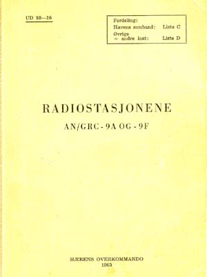
1) Radiostasjonene AN/GRC-9A og 9F (1965).
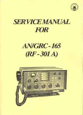
2) AN/GRC-165 (copy available from NRHF)
 |
 |
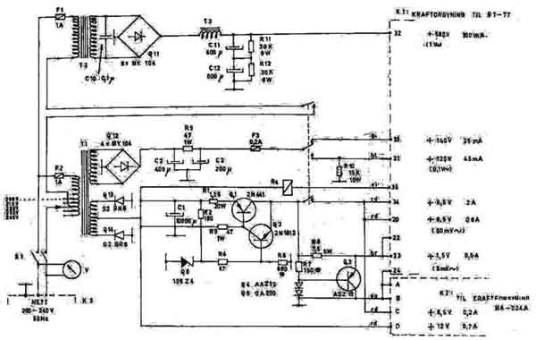
RT-77: Kraftforsyningsenhet
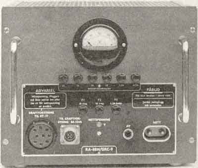
RA-88/GRC-9 (Mains Power Supply Unit for AN/GRC-9A)
Kraftforsyningsenhet RA-88/GRC-9 er beregnet for nominell 220V
50p/s lysnett-drift av radiostasjonen AN/GRC-9A.
Kraftforsyningsenheten leverer alle nødvendige spenninger så
som anode-, filament og nøkkelspenninger til sender og mottaker.
Disse spenninger tas ut over en 9-polet multikontakt på
frontplaten merket "Kraftforsyning til RT-77".
Kraftforsyningsenheten har
dessuten en 4-polet multikontakt som er merket "til
kraftforsyning BA 224A", hvor man tar ut styre- og
rele-spenninger til nettdrevet
kraftforsyningsenhet M-96.
Fabrikant: David Andersen, Oslo
Dette er en gammel ting, og det er dårlig poeng å
prøve å kopiere denne idag.
It is an old construction
for an even older transceiver, but it seems no point in trying to
copy a construction made when
semiconductors were expensive and some bad design techniques were
applied.
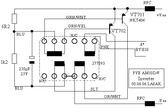
Reusing PYE Cambridge power supply for some other surplus
equipment...
(PYE AM10d, FM10d)
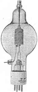 |
Frank's electron Tube Data sheets http://frank.pocnet.net/ 100TH http://frank.pocnet.net/sheets/090/1/100TH.pdf |
RX Intermediate
Frequency List (e11)
Valve equivalent list
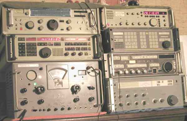
Somebody likes more modern equipment
I enjoy collecting
these items and I will show them on my website for others to
enjoy. I am not interested in selling them, however - please do
not ask.
Instead, I hope to help others who collect this type of gear and
would like to
hear from them.
All incoming mails are filtered
using MailWasher, so please use an
intelligent title so it is possible to distinguish between
friends and spammers.
Last uppdat: 2004.07.08