
g45. RTTY-, Hell- and CW-demodulator techniques
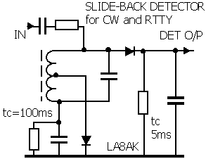
The slide-back detector for better zero crossing for RTTY and CW
detectors. Basic circuit diagram, see also ATC
It is particularly suitable for single frequency signals (ASK -
amplitude shift keying) which was used for telex on telephone
lines.
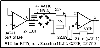
ATC (Automatic threshold control) for better zero transition for
RTTY and CW detectors (time-constants for RTTY)..
First saw it mentioned for Mainline TT/L Terminal unit, this was
described by OZ9JB Jörgen Badstue.
While the slideback-detector has audio input, ATC has DC-signal
from the detector/lowpassfilter.
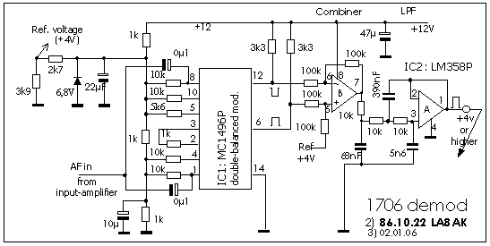
CW demodulator with MC1496P. A double
balanced modulator used to give a variable
DC voltage out dependent of audio input level. Will also work for
higher frequencies.
Some RF decouple capacitors should be connected across the 3300W resistors from pin
6 and 12 to +12V (or to ground).
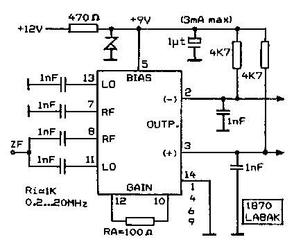
CW demodulator with S042P (sensitive
AF/LF/HF-level detector)
For some experiments I needed a simple and efficient
detector. Had good experience with
MC1496P, but only few left and many Siemens S042P available. The
resistor RA decides
the gain. In spite of small bypass-capacitors it is flat over the
range 0.2-20MHz (RA=100W).
A comparable circuit diagram for use as product detector is shown
on page-c13
| RF input level | DC level at pin 2 | DC level at pin 3 |
| -50dB | 6.91 | 6.95 |
| -40dB (8mV) | 6.89 | 6.97 |
| -30 | 6.73 | 7.12 |
| -26 | 6.48 | 7.36 |
| -23 | 6.17 | 7.66 |
| -20dB (80mV) | 5.77 | 8.04 |
| -17 | 5.35 | 8.44 |
| -15 | 5.11 | 8.6 |
| -13 | 5.01 | 8.75 |
| -10 (250mV) | 4.75 | 8.82V |
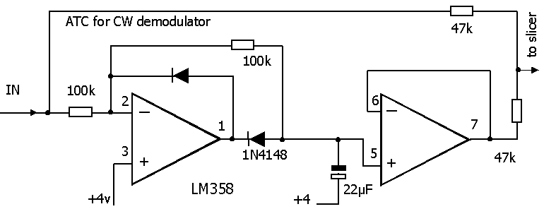
Suggested ATC circuit for CW-demodulator using OP-amps instead of
germanium diode bridge
The circuit is based on +4V as reference voltage (depends on
preceeding stages)