
LwEa und T8PL39
(Telefunken)
LwEa und T8PL39
(Telefunken)
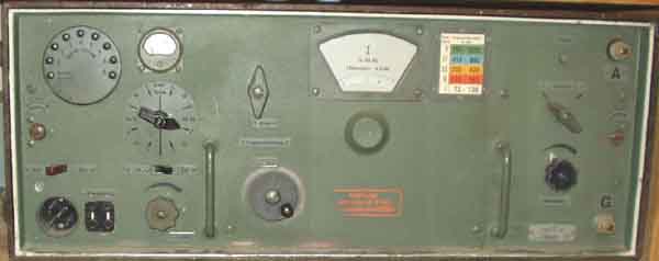
Lw.E.a. front view
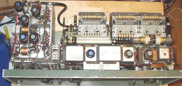
The receiver seen from above,
it looks quite "radio-amateur'ized" with most of the
screen lids missed,
but in facts I got it from Bergen radio (LGN Rundemanen) and the
IF rejection coil - of all things - has
been aligned so many times with bad screw drivers that the core
doesn't look good, but the other cores
are not vandalized - perhaps they didn't dare!
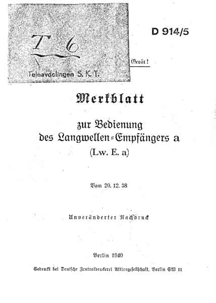
Lw.E.a. -
Langwellenempfänger 'Anton'
I 72-128kHz (wht)
II 122-241kHz (Red)
III 230-430kHz (Yel)
IV 410-800kHz (Blu)
V 760-1525kHz (Grn)
Circuit: 8?x RV2P800 as???
The RX has no AGC, and RF and Audio gain control are combined on
one knob.
IF=60,9 kHz. BFO: 60kHz xtal and 61,8kHz tuned circuit.
NA6/NA6a mains power
supply, EU.d converter for 12V supply
-----
It should be mentioned that
neither any of my Kw.E.a's nor Lw.E.a have needed any sort of
repair,
no capacitors have been found defective in any way. But this may
not indicate that they are not bad in
any ways, they just work satisfactorily. Lw.E.a sounded somewhat
noisy when I tested it last year after
being inactive for many years, but the noise dissappeared after
some days operation. I suppose it was
caused by bad contacts rather than leaky capacitors.
Feldfernschreiber 24a-32 and Torn.Fu.d2 is different
story, while Torn.Fu.b1 seems better in such respect. I got the Lw.E.a at Bergen radio, LGN in
1976.
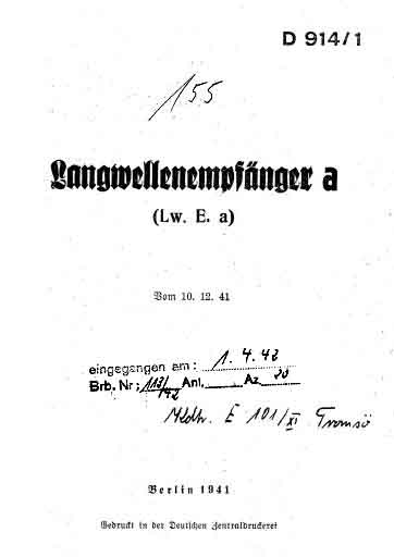
The following files are available, see the
links below (tnx LA6TJA):
D914/1 cover (1278kB)
LwEa_003.pdf (2171kB)
LwEa_Teilliste (1346kB) /la8ak/12345/images/0216_018.pdf
LwEa Schaltbild (827kB) - /la8ak/12345/images/0223_001.pdf
LwEa Vereinfachtes Schaltbild (112kB) - /la8ak/12345/images/0224_001.pdf
LwEa circuit in gif format, see page
n74
Lw.E.a IF filter. It is two similar IF-stages on 60,9kHz. The
circuit is drawn such that the similarities/differences with
Kw.E.a can be seen.
One must consider the bias circuit when
building a power supply for the receiver, similar circuit for
KwEa, FuHEc, FuHEu, TornEb.
 |
 |
 |
 |
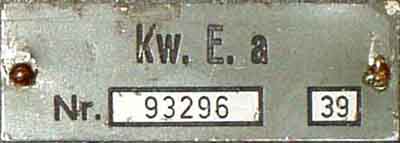
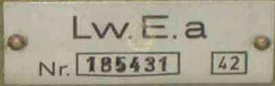
Type plates and
remarks for Kw.E.a and Lw.E.a
 |
 |
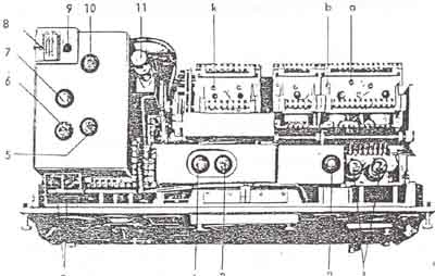
T8PL39. It is funny to see
how much the chassis looks like Lw.E.a
The two TE30 at the far left
side, then RF, Mixer, Osc, 2x IF, detector, audio and BFO at
upper left side.
 |
 |
Functional circuits:
T8PL39 vs. Lw.E.a.
T8PL39
"Martin" (E491 N)
Telefunken
Peilüberlagerungsempfänger,
Kreuzrahmen-Goniometer-Landpeileanlage NVK-GL/39
This is a DF receiver, in-spite of that what the front looks
like, the chassis looks very
much like Lw.E.a. (and Kw.E.a)
The circuit diagram is very much like Lw.E.a, but the valves are
RV12P2000.
It has a 4-section tuning capacitor. Two tuned circuits ahead of
the RF amplifier.
The receiver has the following stages:
RF-amplifier, Mixer, Local Osc., 1st and 2nd IF-amplifiers,
Detector and audio amp.
(diode/triode connected valve), BFO/CAL, Audio output. The
detector/audio amplifier
is very much like E52, but it is no AGC detector. It is two
double tuned IF
bandpassfilters for the selectivity.
Frequency ranges:
I 72,5-119kHz
II 119,0-196kHz
III 196-321kHz
IV 321-527kHz
V 527-860kHz
IF= 60,9kHz
BFO: 60/61,8kHz (60.9 + 0.9kHz). Suppose the pitch is
intended to be 900Hz.
Valves: 8x RV12P2000
Stabilovolt STV75/15 II
Te30 (Osram)
Osram 3766, 6418 and 57.7130 lamps
Sensitivity:
BW Pos 1-5. emission A1A 1-5µV
BW pos.1 emission A2A 5-20µV
Selectivity (3dB bandwidth): 5 steps 300Hz...8kHz.
Band I 1kHz, Band II 1,2kHz, Band III 1,5kHz, Band IV
3kHz, Band V 3,5kHz.
| IF rejection: | Band I minimum 80dB | = 10E-6 ( @ 87kHz) | |
| Image rejection: | 400kHz 10E-6 (60dB) | 200kHz 2*10E-6 (66dB) | 120kHz 4*10E-6(72dB) |
It is two similar IF-stages on 60,9kHz, it seems to be very much
the same as for Lw.E.a, and I would have to check more carefully
later (miss proper docs. for LwEa).
The bandpassfilter circuit is drawn such that the
similarities/differences with Kw.E.a can be seen.
T8PL39. Maße: 340 h, 668 b, Tiefe: 355mm
Goniometer
 Data for RV12P2000 |
 RV2P800 (1) RV2P800 (2) RV2P800 (3) |
 Seefunk+Seeschiffahrt |
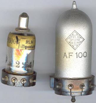
RV12P2000 and the special purpose AF100, it has a somewhat
different socket (8pin) - more like RL4,8P15.
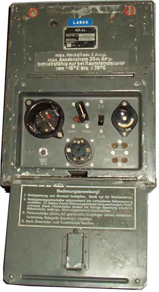
NA6a. The most commonly used power supply for Kw.Ea, Lw.Ea
(and Fu.H.E.c).
A switch adds resistor to compensate for the 0.4A lower filament
current of LwEa (1,8A) compared to 2,2A for KwEa
 |
 |
| Artikler i 'Amatör Radio' og
'OZ': Brug af STV280/40....................................... OZ7AQ OZ 70-04-117 Kw.E.a. Brumfri likeretter for mottakeren....... OE3UK AR 63-04-053 Kw.E.a. Forbedringer for SSB .......................LA8AK AR 73-09-195 Kw.E.a. Kraftforsyning................................... LA4HK AR 71-07-167 Lw.E.a. Reparasjon av mottakeren.................. LA7MI AR 85-10-269 Maling av Wehrmacht og Luftwaffeutstyr......... LA8AK AR 95-02-044 RV12P2000 og RV12P2001 brukes i nyeste mottakere AR 51-09-246 Sirutor 5a og 5b dioder, erstatning .... LA4OE, LA8AK AR 95-02-044 |
 Solidstate supply ideas for 12V operation |
I enjoy collecting these items and
I will show them on my website for others to enjoy. I am not
interested in selling them, however - please do not ask.
Instead, I hope to help others who collect this type of gear and
would like to hear from them.
All incoming mails are filtered
using MailWasher, so please use an intelligent title so
it is possible to distinguish between friends and spammers.

Correspondence: You may write in English or German, Danish or
Swedish, but I will reply in English (or Norwegian)
2005.02.10