
Modern Zwischenbasis amplifier(*) for
Mixer IF termination
c19.
Moderne Zwischenbasisverstärker für ZF
 see previous notes and history details
 |
 |
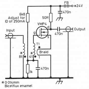
The basic low-noise, high-intercept-point
amplifier with gate-source feedback and using the
discontinued
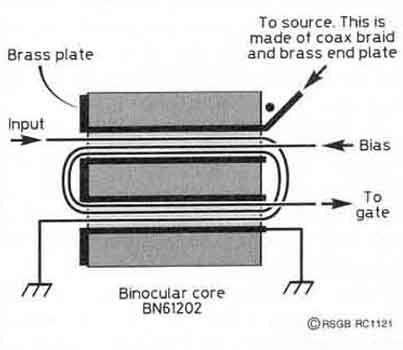
Siliconix VMP4 power FET as implemented by W4ZCB. To minimise
leakage inductance, the single turn
braid must use brass end plates so the braid can be opened up and
pushed into contact with the sides of the
hole in the binocular core. However, reasonable results can be
obtained with just the braided with enamel
inside and no end plates. (Reference 3)
Alternative circuit with 2N5109 has IP3=17dBm on page n16
ZB-references:
1) Zwischen-Basis amplifier with J308 2) G3SBI Radcom TT Dec 95
pp70-71
2) Zwischen-Basis cascode-amp. with J310 1) G3SBI Radcom TT May
95 pp60
3) Zwischenbasis amplifier W4ZCB and G3SBI Radcom TT Sept 96
pp70-71
4) Zwischen-Basis JFET amplifier 4) G3SBI Radcom TT Sep 98 pp
58-59
5) ZB: Transistor-Konverter für 145MHz DJ2LR UKW berichte 1/64
pp.1-3
See more similar notes found in recent Radcom
and other magazines
pg n16. LA7MI
highlevel mixer experiments and notes
Stein Torp, LA7MI made some calculation to find
the formula to calculate the input impedance for a known fet
(20mmho) with different
turns ratios, where (for simpler calculation) the source is
tapped 1 turn from center tap, and the gate winding is varied.
He sent me a letter where he shows how to find the expression,
but I haven't found all the proper symbols, so only the
conclusion is shown
(2003.05.31 LA7MI)
Leif Hansen, LA6LCA suggests using MRF134 FETs for higher order
IP3, see the note below.
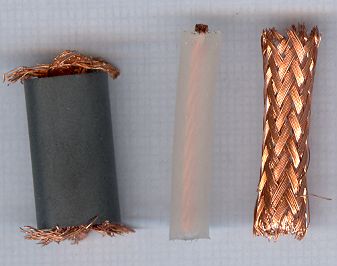
I am not sure it is neccessary to go into the mess using brass or
copper tube for the single winding, I've just tested another
transformer using coax braid instead, perhaps equal transformer,
but it is an indication that it might work well.., see page n16. Core
info: Philips 3122 134 90783 Ferrite grade 4A4 permeability 500.
4v per turn at 80m band gave 20°C temperature increase. 1 turn =
0.9µH, O.D.= 10.5 mm, I.D. = 6.9 mm, 19.5 Long (LA8AK)
2m RX pre-amp using MRF134. The device needs 100-150mA for low
noise figure, maximum voltage 28VDC. Suggest to use a constant
current circuit as shown, but only a simple circuit is shown,
some optimization of input impedances is neccessary for optimum
noise factor (LA6LCA).
See also the VHF notes on page d12.
LA7MI has experimented further with Zwischenbasis amplifiers and
here is his DG-FET version for 10.7MHz
The 10,7MHz amplifier has 18dB gain (50 ohm). Noise factor is
supposed to be 2dB. Input return loss is 20dB, it may be
optimized by changing the 2700pF capacitor.
Coils on input and output are wound on Amidon T50-2 cores.
Trimming is done with stretching and pushing the turns on the
toroids. He has used
SMD components, didn't notice any sign of instabilities or
oscillations, the 47W resistor in gate
2 is important to avoid spurious instabilities. (LA7MI Stein Torp
2003.06.03)
NOTE *) Zwischenbasis
amplifiers were first described by Cantz in Telefunken
Mitteilungen 1953. The German name is not easy to translate to
other languages.

2004.10.24