
b92. Storno CQF/CQM/CQP600 mods
Storno
CQM612 is
the 2m rig I like the best, my experience as professional is with
CQF612,
and in amateur radio packet radio using CQP612, and CQM612 is the
best because it has
space for 230VAC power supply and it is no need for the rather
heavy CQF612.
If you have many similar rigs in the same rack, CQP612 has the
advantage that the front is
smaller than any of the other Storno 600 rigs, and when modified
they can share the same
power supply unit, but you must not try so without
modification!
I've worked with the CQF612 a lot, and had to carry lots of them
to oil platforms in the North Sea
in the 70's where we used them for radio link to shore purposes.
The only reason for using the
CQF612 is if it has a 25W power amplifier. Have modified and used
almost a douzen
CQM/CQP612 for packet radio nodes. CQM612 is also well screened
between receiver and
transmitter and, as such very useful for voice-repeaters.
The only reason for salvaging a CQF612 is that some models has
PA614 25W RF PA-module.
The PA612 also has 25W RF, but they had problems and were taken
out of service many years
ago. The 8, or 9MHz IF stages may be retuned to 10.7MHz, but I
don't really see the point, and it
was a lot of spares available for 10.7MHz.
Even with the relay to switch -24V it lasts very long, but it was
changed in all my rigs, and I used
diode switched antenna connection.
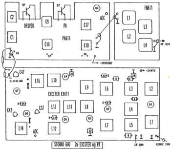
CQM612/CQP612 2m rig
- transmitter RF section
CQM612 Power supply #1.
For CQM612 it seems to be a good idea to use the
regulator from CQP612.
The floating ground inside the set isn't any problem (in contrast
to CQP612). In this case the transformer was somewhat too small
for the application, so RF power output was reduced to 5W.
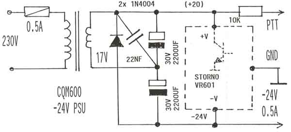
CQM612 Power supply #2.
Another power supply for
CQM612 uses a 28V transformer, 7924 type negative regulator. The
positive voltage for PTT circuit is made with an extra voltage
doubler circuit (2x 1N4007) with a zener diode to limit the
output voltage, this is not critical at all, will work with any
zener voltage between 6 and 15V, and the voltage need not really
be stable to work perfect. A 2N7006 switch fet is used because I
got some hundreds from LA3VW, many other types will work.
The output from the capacitor on the lower right side is to the
xtal oscillator board. RX and TX oscillators may run continously
(and should for better stability) - provided some steps are taken
using a diode switch to prevent TX signal to spread into the
receiver.
 |
 |
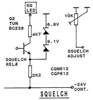
CQM/CQP612 . Two versions of squelch indicators for LED,
and connection for squelch-adjustment potmeter.
CQP612 Power
regulator.
CQP612.The rig is meant to operate with internal battery
which is charged. But I operated it stationary for packet radio
node.
It is a problem to use this rig with external supply because it
uses floating positive voltage.
I removed the rubbish, and the regulator may well prove useful
for CQM612 instead. It is better to use a negative voltage only,
-28....33V is suitable. But the rig needs a positive voltage for
the PTT operation, and it is easy to make with an oscillator
consisting
of a uA741. The antenna relay is actually quite good and lasted
long - even for packet radio operation.
CQP612 (CQM612). To avoid TX frequency drift it is a good idea to run the TX xtal
oscillator continiously,
but an RF switch must be added to avoid some weak interference
signal into the receiver.
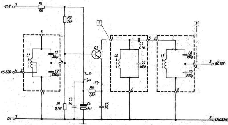
Here is shown oscillators for the 24-channel versions with
12-13MHz RX osc and 8-9MHz IF, while the standard version
has 10.7MHz IF and a 45 or 51MHz xtal osc. The main intention is
to show the transmitter modication, while RX oscillator,
is not important in this respect.
To simplify it is no problem to use the same oscillator board for
either oscillators, or
group of oscillators, but I've only used single channel Storno
rigs.
** NOTE: The circuit diagram seems to be unclear, but the 47W
resistor is connected in series with the
4700W resistor (to -24V TX) and 10nF (.01) cap to
ground. The resistor in parallel with 20(22)pF is 2200W.
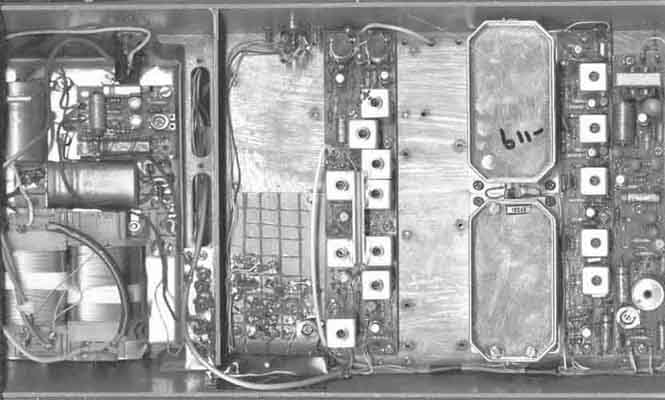
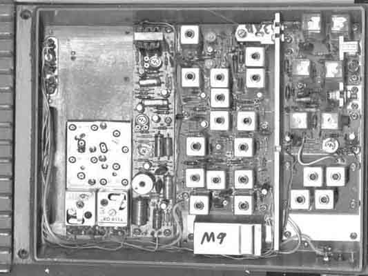
CQM612 seen from below (the rig is slightly
larger than the scanner). It is a standard version
(10.7MHz first IF), it has no extra oscillator multiplier board.
The power supply unit is
completely renewed, but uses the voltage regulator from CQP612.
Because of the lower efficiency
with mains transformer with voltage doubler the RF power is
reduced to 6W.
You may see the 5-pin DIN connector mounted near the RF input
coils, the mains fuse and that
the old multiconnector is removed and replaced by a aluminium
plate with rubber grommet and
mains cable. A modifcation board and 4 LEDs are also installed.
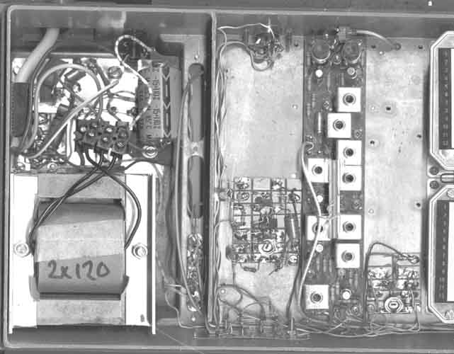
CQM612 seen from above. It has few modifications, but
XO611a and XO631a is installed on
the same plate, and the oscillators has constant supply voltage
during receive- and transmit-modes.
It is possible with an extra diode-switch. The original antenna
relay is kept
CQM612. Here shown with normal type power supply, 24VAC
transformer and 7924 regulator.
It is also a modulation indicating amplifier (uA723) and squelch
indicator.
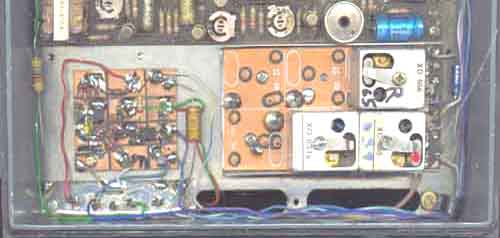
CQM612. A PTT switch using 2N7006 is used in this
version. Also used FT-capacitors between the
two halves of the rig to protect against RF leakage and stray.
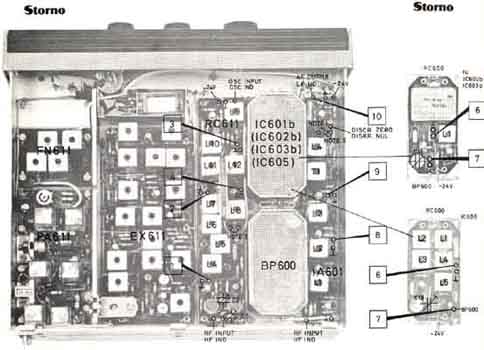
CQP612 - picture from the handbook. CQP612 is a
handy rig, and the advantage is that it has
a smaller front than the other and it is possible to mount a
meter and LEDs here. But powersupply
demand is a problem, since it uses external DC. The original
version must have galvanically
isolated 30VDC or higher supply voltage, so it is a good reason
for changing to -30V with grounded
positive side. Then several rigs may be operated from the same
source. It is in most ways
electrically the same as CQM612, especially when modified and all
unneccessary functions and
boards removed. Some rigs have 9MHz IF (Denmark) and 8MHz
(Norway) such that each crystal
can be used for either RX and TX - with maximum 24 channels, but
amateurs have not 8 or 9MHz
DX-distance between RX and TX frequencies and will only have max
12 channels. the 8 or 9Mhz IF may
easily be tuned to 10.7MHz, but I don't really see the point. And
since these units don't have
xtal filter in the first IF they are better suited for 9600baud
packet radio.
CQP612 (CQF612/CQM612) ADC problem
It is a very bad idea to rely on the ADC when tuning the rig to a
new frequency. Most likely you will
destroy part of the power amplifier. The ADC will only protect
the output transistor, but the driver may
still be pushed to hard and a resistor in base circuit is likely
to burn out - and it takes some time
to replace. It is easier to modify the AGC permanently or
temporarily to set a limit to the drive
level as you tune the transmitter. Here is a manual gain control
with connection to the adc line,
so the adc may have influence to it when antenna is defective
CQP612 (CQM612) - illustration for how wrong a single
12MHz xtal would work.
The 24-channel version will not operate on 2m without modication,
it has common "12MHz" xtal
osc for RX and TX. It is important to install separate
oscillators for RX and TX, but may be housed
on the same board - with an RF switch as mentioned above. The
24-Ch versions have different
RF-converter with 25-28MHz local osc input, and multiplies by 6
instead of the normal 3. And
another doubler is used to double 12.5-14MHz signal. RX and TX
uses the same type of oscillator,
and it seems no good idea to take the work to change this. The
Danish IF is 9MHz, and the
Norwegian IF is 8, this is identical to the duplex distance. The
normal receiver uses an xtal
filter while this version uses an LC-filter, but it is broader
and far better for 9600baud packet
radio
CQP612 freqency doubler FD611a-6471/6471a (similar,
but not identical to FD for CQM612)
Frequncy range (specified):
Input frequency range: 13.31-13.4MHz, output freq.
26.620-26.800MHz, BW: 200kHz
(all I have tested covers larger frequency range below 13MHz than
specified).
Gain @60mV RMS input: +20dB
Measures 68x32mm. The doublers for CQM612 and CQP612 are
different mechanically, but
electrically equivalent. Supply: -24V 2.5mA
The RF converter RC612 for has 25MHz input instead of 45MHz for
RC611
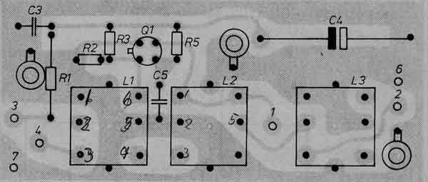
CQP612 frequency doubler FD611a-6471/6471a
1. Test point
2. Test point
3. -24V
4. Input from XS600
5. Output to RC612
6. GND
7. GND
CQP612-6477a (for Norwegian 24-ch public VHF mobile
telephone system).
Storno 24ch version CQP612, which apart from the power
supply and mike-, and external connections has
the same functions as CQM612. I've converted 2 different CQP612
(24 and 12ch versions for Norway) and
several standard CQM612 (and one Danish 24channel type with 9MHz
xtal osc). Since it was easy to get
spares then, I converted some of the 24channel versions to
10.7MHz, but kept the xtal oscillator arrangements.
Source: CQM612. Appendix
T117330. Bærbart radiotelefonanlæg Model Stornophone 600, type
CQP612-6477a. I have seen no handbook
for CQM612, only CQF612 and CQM612-6477a.
Calculating
2m RX xtal frequency (CQF/CQM/CQP612):
Normal 2m RX xtal:
(145-10.7)/3 = 44.76667MHz (CQF612)
This may or may not work, and may need some modifications, so I
didn't find it interesting since I only operated single channel
rigs.
Standard version Storno,
choosing RX xtal frequency for minimum plunder when the rig was
used on 160/170MHz before..
(145+10.7)/3= 51.900MHz. (Possible to modify for lower xtal
frequency, but a chance that it will cause some problems to
solve).
Modified 24ch version with 10.7MHz IF:
(145+10.7)/12 = 12.975MHz. * Input to RC612:
25.950MHz.
Modified 24ch version with 9 MHz IF*: (145+9)/12
= 12.8333MHz. * Input to RC612: 25.6666MHz.
Modified 24ch version with 8 MHz IF*: (145+8)/12
= 12.750MHz. * Input to RC612: 25.500MHz.
*) 8MHz IF was used for 24ch. CQP612/CQM612 PMRs in Norway, while
9MHz was used in Denmark. The same xtal was used for RX and TX,
with an extra multiplier for
the RX local oscillator, but this has large frequency coverage
and covers the different IF frequencies whether the oscillator is
above or below the RF frequency. So when
the rig is converted to amateur band operation, it can only take
12 xtals for RX and another 12 xtals for TX. The RF
converter RC612 for has 25MHz input instead of 45MHz for RC611
TX xtal frequency: (145/12) = 12.08333MHz
Calculations
for Storno CQM/CQP662:
RX (10.7MHz IF): (433-10.7)/9 = 46.9222 or (433+10.7)/9
= 49.3000 MHz
TX: 433/36 = 12.027778 MHz
See technical reflections #68, Amatör Radio for further info
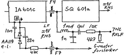
S-meter and audio output for TNC2 (CQP612).
Tested this circuit, but the problem is that the best OP-amp to
amplify negative voltages is µA741, and it is not so good so it
won't amplify lower voltages than 0.5V below ground with -24V
supply voltage
Since CQM612 and CQF612, it is possible to make the same circuit
for these, but hey have no front and as such
not so good idea to build it. (890404)
One of the DC amplifier circuit used is shown here.
A modulation instrument circuit is shown here, it is no real
problems, but sensitivity may need to be adjusted
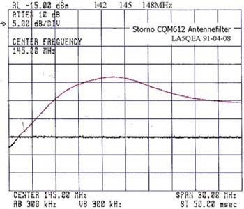
CQM/CQP612 Antenna filter, measured by LA5QEA, Ralf

2004.07.20