Heath-Kit mods

Heath MR1 AGC-experiments
Quite early caught interest for proper AGC circuits. Noticed
OZ7BQ's circuit described in OZ nr 2/64 for Heath
MR1 "Comanche". This is the first
reference I have for this type of circuit. It certainly have some
of the same
ideas found in Drake TR-4 (and TR-3 ?), but at this stage Drake
used 12AT7/ECC81 or 12AX7 for the detector.
The reason for showing this circuit is only as a reference for an
idea which has been shown in the early 60's. You will find much
better solution in Drake R-4B or 2-C, and a somewhat more
optimized version in R-4C, but it might not be so easy to use in
any receiver, a better transistor is BC547 or 2N4401, and the
output resistors could be increased to the meg-ohm range - or
say, just as usually found in any receivers.
Heath Kit SB-300 and
SB-301
At the moment my documents are not available, so I don't
have any papers available, but will give details
as I remember it. I had an SB-300 in 1967-68, later did some
checks and mods on SB-301.

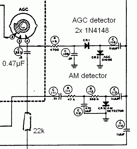
The AGC-detector. The
problem is low IF output level and you need to take where it is
possible. The AGC-detector-diodes
were not good type. Replaced it and AGC detection was much
improved. Suppose the old diode had too high internal
capacitance. At the moment I checked the AGC I had lot of
experience with Drake 2-B, and had improved Trio TS500
rather much, suppose I used 1N4148 diodes. It is also a good idea
to increase C223 to 0.47µF and add a 22k resistor in series for
faster agc attack on ssb.
RF stage intermodulation.
Several reports were discussed in Radcom TT, and some reported
that they
cured the receiver by connecting 6BA6 directly to the input
circuit, rather than using the grid resistor to AGC-
line. But with an AGC which doesn't swing sufficient as it was,
all the stages should be connected to AGC.
Removing AGC to the RF amplifier is a bad idea - when it is still
possible to avoid it.

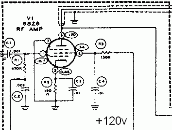
The problem with 6BZ6 is that it is run with only 0.45V cathode
voltage (and too high impedance grid circuit). This is overcome
if you increase the voltage
drop in the cathode resistor to 1.5V, possible resistor value 470
ohm, but then you must increase the screen voltage from 60 to
90-100V (from +120V source),
the 150k was replaced with 10k(?), and you will see that grid
current is no problem..

2005.03.06