
ICOM IC-202E [IC-202S]
IC202E is my 2nd 2m rig, I use it mainly for
mobile operation with a 25W linear amplifier. The rig is small
and have better reputation than it deserves, but as a second rig
it is not so much used and it not much - if any - strongsignal
problems in this area or places I've operated from. For mobile it
is neccessary to use headphones when driving, otherwise it is
impossible to hear what the opposite operator says.
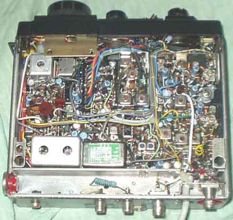 Antenna removed to add some space |
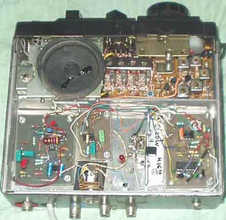 Battery holder removed... |
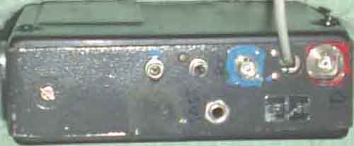
IC202E rear view. 2x BNC-connectors, Blue: RX
Ant, Red: TX Ant., 2x RCA phono jacks and standard KEY/PTT
jack
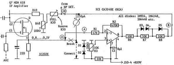
IC202E S-meter modification. Remove R50 labelled
"FULL".
| RF dBm | µV p.d. | S-unit reading | difference | dB/S-unit |
| -120 | 0.22 | S0 | - | - |
| -115 | 0.4 | S1 | 5dB | 2.5dB/S |
| -110 | 0.7 | S3 | 5 | 2.5 |
| -106 | 1.1 | S5 | 4 | 2 |
| -102 | 1.8 | S7 | 5 | 2 |
| -97 | 3.2 | S9 | 5 | 2.5 |
| -89 | 8 | S9+10 | 8 | 80% |
| -80 | 23 | S9+20 | 9 | 90% |
| -69dBm | 80µV | S9+30 | 11 | 110% |
| -57 | 316µV | S9+40 | 12 | |
| -37 | 3.160mV | S9+60 | 20dB |
S-meter readings after modification
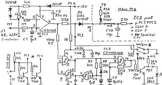
SSB/CW squelch for IC202 based on signal to the S-meter
Using IC202E in more complex environment.
The original circuit for PA and RX antenna switching is shown,
the diode D25 connects the signal to RX for receiving, and a
smaller DC-voltage is available on the antenna connector. This
voltage may be used to switch external equipment, but it is
somewhat impractical because it might give a missed signal to
switch to transmit. Better is to have a positive signal on
transmit, and if the signal is broken nothing happens - only the
exciter (IC202) is switched to transmit, but no harm to the power
amplifier, still the pre-amplifier need some backward protection.
I found it more practical to use a separate connector for receive
- the original connection is also bad for noise figure, and a dc
voltage through a resistor is fed to the TX connector. The
original connector is used for transmit, and another BNC
connector is used for receive. Dide D25 is left open in one side
or removed, and the cable from RX now goes to RX-connector. A 4k7
resistor from +TX 12V goes to TX-connector.
I have lost the circuit diagrams for modifications.
IC202E PTT modification Ver. II (89-07-17). Using external PTT
control for CW-operation.
Remove D17, R55, PTT connection to Mode-sw S3
Connect 1N4002 in series with R54, 22k from Q12 emitter to Q13
base, 10k from Q13 base to ground.
Note: Q12 in IC202E is Q11 in IC202S, Q13 in IC202E is Q12 in
IC202S
Es stand in der CQ-DL, Band 2, Testberichte
A really very interesting book from DARC showing
testreports by DL1BU for the following equipment:
Atlas 210/215, CRF320, Drake R-4C, Dressler D200, FT-221, FT-301,
FT-901,
IC-202S, IC-211, IC245E, IC-280E, IC402, IC-701, KDK FM 2015R,
KDK FM2016E,
LT470 (Braun), Multi 2700, REIS SE200XL-A, SB-104, SE301 (Braun),
TS-520, TS-820,
Vergleichtest FR101, FT-220, FT221, HG70D, IC201, Multi2000,
Multi2700
CQ-DL 3/79: 3-Watt-Kleintransceiver für SSB und CW von Icom
IC-202S für 144MHz, IC-402 für 432MHz [DL1BU, Günter
Schwarzbeck]

2005.03.05