
23r) Philips portable WWII equipment
DR25b, DR38, DR42, DR78, DR85, DRG4
23r)
Philips portable WWII equipment
DR25b, DR38, DR42, DR78, DR85, DRG4
Links to other actual pages:
11a. Main page for German Receivers
11c Index to surplus equipment described
on this site
23q Philips HMZL34/OKM
23s Philips commnication receiver
BX925
53a. Main page for Dutch WWII equipment
The document shown below is largely based on info from Jean-Noel
Bienfait, except for DR38.
DR25b [PHI 1 UK 41] VHF portable transceiver
- history and relationships.
For more details about Philips Factory history during WWII,
please see:
http://www.digidome.nl/philips_1940-1945.htm
The DR25b1X is a unit, that seems to be derived from different
Philips/ NSF sets, probably
made for different purposes before the war.
The table hereafter provides an overview of other Dutch sets that
were made by Philips before or during WWII.
| Type | Model | Refr (+ Betriebsart) | Freq. coverage | Valves | Power requirement |
| DR 25 b1X | UK 41, UK 43 | PHI A3 | 37.5 - 46.2MHz | 2x KDD 1 2x DF 25 |
1W S/E 4.5V/35V |
| DR 38 | --N/A | PHI A2, 3 | 66 - 75MHz | TE 05/10, EL 5, 4671, 4672, ELL 1 |
4W S/E 6V battery |
| DR 42 | --N/A | NSF | 195 - 205MHz | -- | 2W |
| DR78 | --N/A | PHI | 3.0 - 6.0MHz | S: 3x TC 05/5, L4018D E: 6x D1F , 7475 |
|
| DR 85 | --N/A | A2,3 | 30 - 34MHz | -- | 80kW - S |
| DRG 4 | --N/A | PIN F3 | 486 - 549MHz | 20W-Richtfunk |
N/A = Not available
PHI 1 UK 43 = DR25b1X VHF transceiver
(37.5-46.2MHz) circuit diagram (Philips Berlin).
The valves seem to be applied as follows.
Sender: DF25 (Mik.Verstärker), KDD1
(Modulator), KDD1 (Senderstufe).
Empfänger: DF25 [HF-Verstärker], KDD1
[Audionröhr], DF25 [NF-Vestärker], KDD1 [NF Endstufe].
 |
 |
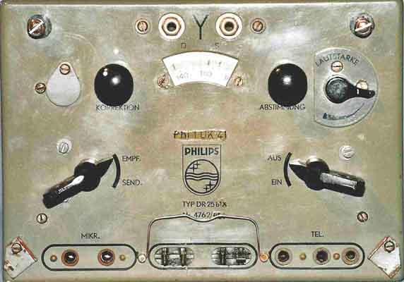
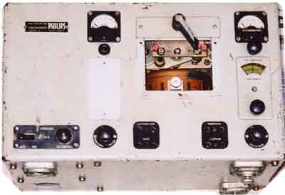
DR25b seen from front and left side (UK41)
 |
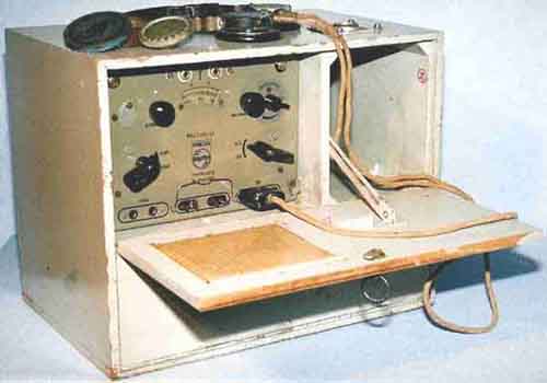 |
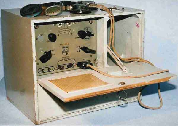
DR25b1X installed in cabinet seen from front
 |
 |
 |
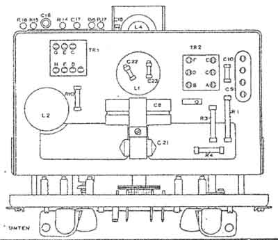 |
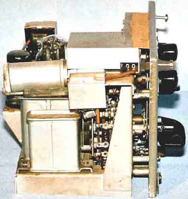
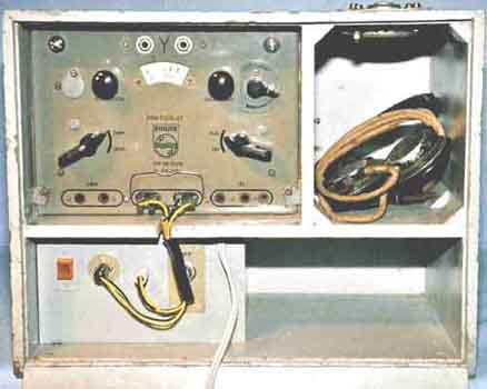
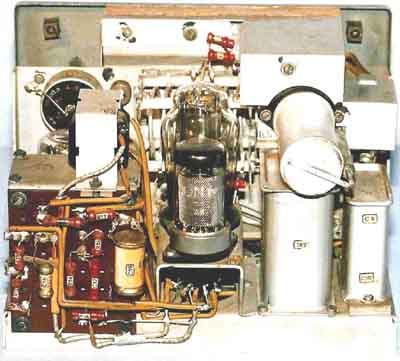
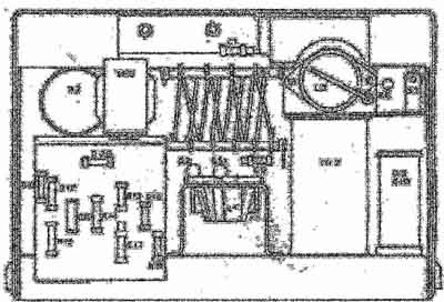
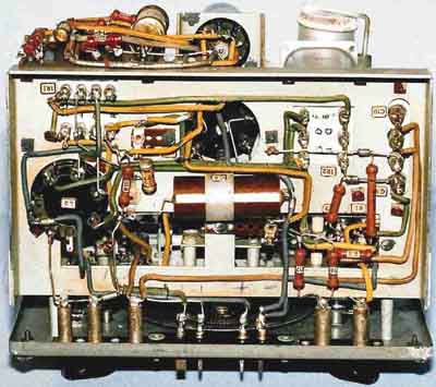
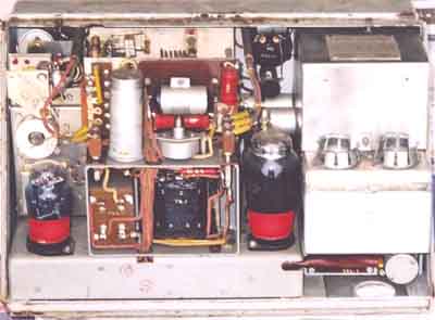
Philips DR25b1X seen from rear and from below. The photos show the UK41 model, while the drawings show UK43.
 |
 |
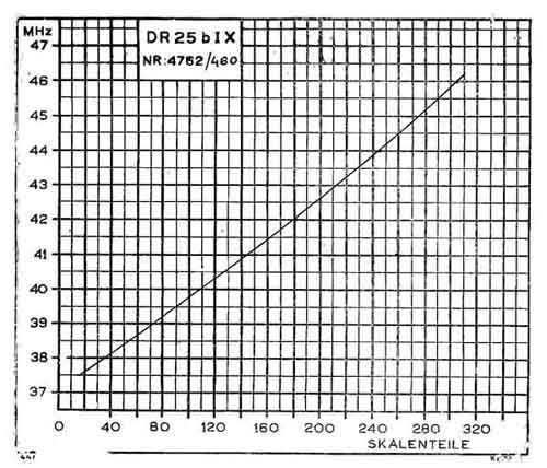
Philips DR25b1X (UK43) scale calibration chart and logo
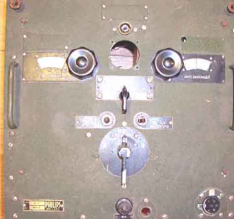
Philips VHF transceiver DR38 (66-75MHz)
- 4-Watt.
 |
 |
Röhrenbestückung, Sender: TE05/10,
EL5. Empfänger: 4672, 4671, ELL1
[Note: 4672 = 954 = E1F, 4671 = 955 = E1C]
Additional information about DR38 development can be found
in the following URLs:
http://home.hccnet.nl/l.meulstee/mobilophone/mobilophone.html
http://www.xs4all.nl/~levend/tvmuseum/tvmuseumnsf/nsfdingen05.htm
DR42 wreck was sold at last NRHF auction in
october 2003. (Picture: LA5CL Tore Moe)
 Better picture (Museum "Waalsdorp") at http://www.tno.nl/instit/fel/museum/images/com7-3.jpg |
 Better picture (Museum "Waalsdorp") at http://www.tno.nl/instit/fel/museum/images/com7-4.jpg |
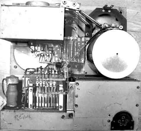
NSF DR42 (195-205MHz transceiver - 4-Watt).
It seems to be the same valves as for DR38 above.
Additional information about DR42 development can be found in the
following URLs:
NSF-factory showing the H2L/7 (among other things)
http://www.xs4all.nl/~levend/tvmuseum/tvmuseumnsf/nsfdingen01.htm
Further infos for equipment and valves are also found in "Kommerzielle
Nachrichtengeräte
von 1914-1945" - Edition 2000/2001 by Gerhard B.
Salzmann, DL2IE
Page last update: 2004.06.11